STM32 HAL Tutorial: Interfacing with Sensors and Devices via I2C
Abstract
Learn how to configure I2C communication on STM32 using CubeMX and HAL drivers. Step-by-step guide for reading sensor data and sending it via UART.
1. Introduction
You’ll learn about I2C (Inter-Integrated Circuit), a widely used serial protocol for connecting STM32 to:
- Sensors (e.g., Temperature, MEMS, etc.)
- LCD/OLED displays
- EEPROM or other microcontrollers
By the end of this episode, you’ll be able to:
- Configure STM32 I2C peripheral using CubeMX.
- Read data from an I2C sensor using HAL drivers.
- Send the sensor data via UART for monitoring.
2. Prerequisites
- STM32 board with exposed I2C pins (SCL/SDA).
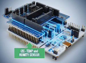
- I2C sensor or device (HTS221 in this case).
- STM32CubeIDE installed.
- Knowledge of GPIO, UART, and timers.
3. Configuring I2C in CubeMX
Step 1 – Open Project
- Create a new project in STM32CubeMX.
Step 2 – Enable I²C Peripheral
- Go to Pinout & Configuration
- Select the I2C available on your board, in this case I2C1, PB8/PB9.
- Assign SCL and SDA pins according to your board layout.
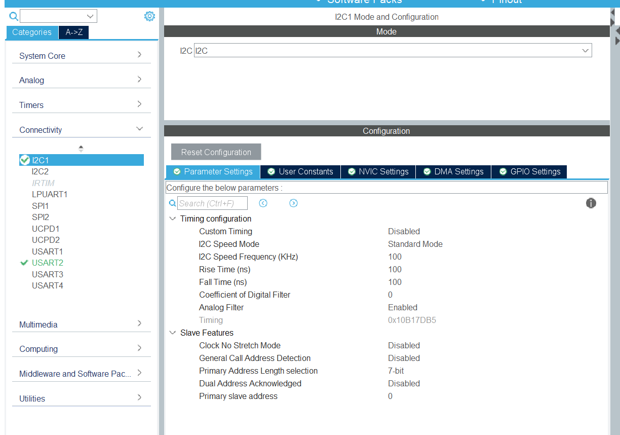
Step 3 – Configure I2C Parameters
- Click I2C1 → Parameter Settings:
- Timing: Use CubeMX’s recommended value or calculate based on clock.
- Addressing Mode: 7-bit (most common).
- Own Address: Not needed for master mode.
Step 4 – Enable NVIC Interrupt (Optional)
- For interrupt-based I2C, enable I2C1 Event and Error Interrupts.
- For Data Ready, configure PA10 as EXTI10 (optional)
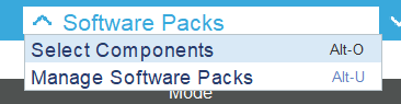
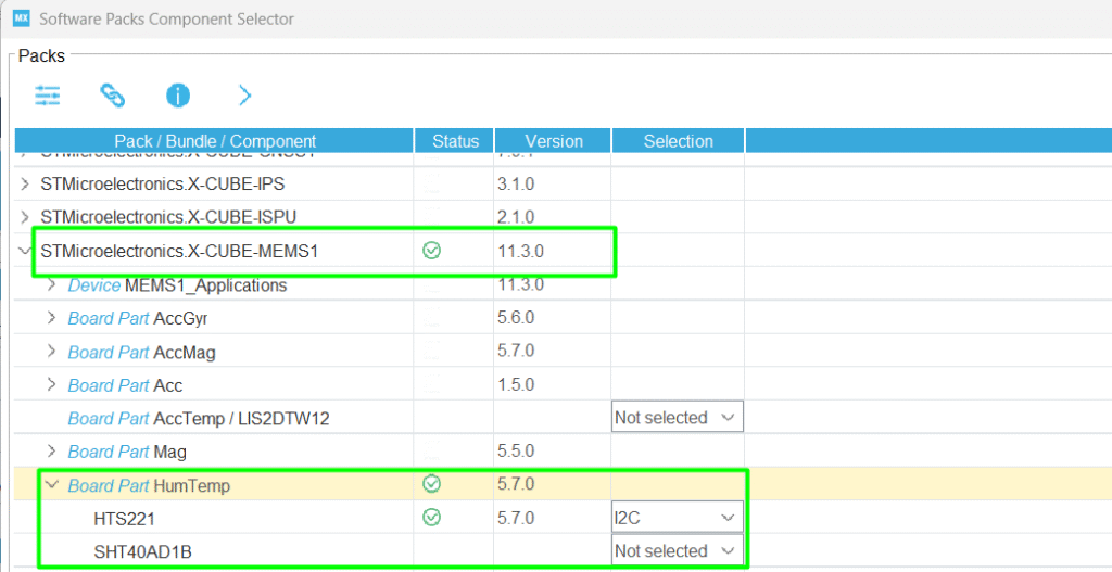
Step 5 – Add the HTS221 support via Software Package
- Click Software Packs → Select Components to initialize the Humidity Temperature.
- Select the HTS221 via I2C
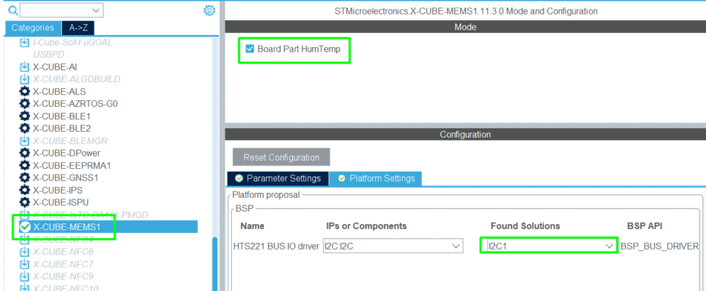
Step 6 – Middleware and Software Packs
- Locate the X-CUBE-MEMS1 and configure it to use I2C1
Step 7 – Generate Code
- Click Project → Generate Code to initialize HAL I2C structures.
4. Reading Data from an I²C Sensor
Step 1 – Download the main application code from HTS221
- STMems_Standard_C_drivers/hts221_STdC/examples/hts221_read_data_polling.c at master · STMicroelectronics/STMems_Standard_C_drivers
- Integrate its content to your main.c file
Step 2 – Read Sensor Registers by polling
- Implement the code in the main.c file, make sure to add the includes and functions. The hts221_read_data_polling()can be added in the main loop.
Step 3 – Monitor via print/uart
- Data converted from the sensors will be transmitted on the terminal, including the temperature and pressure.
Full Source Code: hackerembedded/STM32_EP7
main.c
					/* USER CODE BEGIN Header */
/**
  ******************************************************************************
  * @file           : main.c
  * @brief          : Main program body
  ******************************************************************************
  * @attention
  *
  * Copyright (c) 2025 STMicroelectronics.
  * All rights reserved.
  *
  * This software is licensed under terms that can be found in the LICENSE file
  * in the root directory of this software component.
  * If no LICENSE file comes with this software, it is provided AS-IS.
  *
  ******************************************************************************
  */
/* USER CODE END Header */
/* Includes ------------------------------------------------------------------*/
#include "main.h"
#include "usart.h"
#include "gpio.h"

/* Private includes ----------------------------------------------------------*/
/* USER CODE BEGIN Includes */
#include "stdio.h"
#include <string.h>
#include <math.h>
#include "hts221_reg.h"
#include "custom_bus.h"
/* USER CODE END Includes */

/* Private typedef -----------------------------------------------------------*/
/* USER CODE BEGIN PTD */

/* USER CODE END PTD */

/* Private define ------------------------------------------------------------*/
/* USER CODE BEGIN PD */
#define SENSOR_BUS hi2c1
/* USER CODE END PD */

/* Private macro -------------------------------------------------------------*/
/* USER CODE BEGIN PM */

/* USER CODE END PM */

/* Private variables ---------------------------------------------------------*/

/* USER CODE BEGIN PV */
int __io_putchar(int ch)
{
	HAL_UART_Transmit(&huart2, (uint8_t *)&ch, 1, 10);
	return ch;
}

static int16_t data_raw_humidity;
static int16_t data_raw_temperature;
static float_t humidity_perc;
static float_t temperature_degC;
static uint8_t whoamI;
static uint8_t tx_buffer[1000];
/* USER CODE END PV */

/* Private function prototypes -----------------------------------------------*/
void SystemClock_Config(void);
/* USER CODE BEGIN PFP */
static int32_t platform_write(void *handle, uint8_t reg, const uint8_t *bufp,
                              uint16_t len);
static int32_t platform_read(void *handle, uint8_t reg, uint8_t *bufp,
                             uint16_t len);
static void tx_com(uint8_t *tx_buffer, uint16_t len);
static void platform_delay(uint32_t ms);
static void platform_init(void);

/*
 *  Function used to apply coefficient
 */
typedef struct {
  float_t x0;
  float_t y0;
  float_t x1;
  float_t y1;
} lin_t;

float_t linear_interpolation(lin_t *lin, int16_t x)
{
  return ((lin->y1 - lin->y0) * x + ((lin->x1 * lin->y0) -
                                     (lin->x0 * lin->y1)))
         / (lin->x1 - lin->x0);
}
/* USER CODE END PFP */

/* Private user code ---------------------------------------------------------*/
/* USER CODE BEGIN 0 */
/* Main Example --------------------------------------------------------------*/
void hts221_read_data_polling(void)
{
	/* Initialize platform specific hardware */
	platform_init();
	/* Initialize mems driver interface */
	stmdev_ctx_t dev_ctx;
	dev_ctx.write_reg = platform_write;
	dev_ctx.read_reg = platform_read;
	dev_ctx.mdelay = platform_delay;
	dev_ctx.handle = &SENSOR_BUS;
	/* Check device ID */
	whoamI = 0;
	hts221_device_id_get(&dev_ctx, &whoamI);

	if ( whoamI != HTS221_ID )
		while (1); /*manage here device not found */

	/* Read humidity calibration coefficient */
	lin_t lin_hum;
	hts221_hum_adc_point_0_get(&dev_ctx, &lin_hum.x0);
	hts221_hum_rh_point_0_get(&dev_ctx, &lin_hum.y0);
	hts221_hum_adc_point_1_get(&dev_ctx, &lin_hum.x1);
	hts221_hum_rh_point_1_get(&dev_ctx, &lin_hum.y1);
	/* Read temperature calibration coefficient */
	lin_t lin_temp;
	hts221_temp_adc_point_0_get(&dev_ctx, &lin_temp.x0);
	hts221_temp_deg_point_0_get(&dev_ctx, &lin_temp.y0);
	hts221_temp_adc_point_1_get(&dev_ctx, &lin_temp.x1);
	hts221_temp_deg_point_1_get(&dev_ctx, &lin_temp.y1);
	/* Enable Block Data Update */
	hts221_block_data_update_set(&dev_ctx, PROPERTY_ENABLE);
	/* Set Output Data Rate */
	hts221_data_rate_set(&dev_ctx, HTS221_ODR_1Hz);
	/* Device power on */
	hts221_power_on_set(&dev_ctx, PROPERTY_ENABLE);

	/* Read samples in polling mode */
	while (1) {
		/* Read output only if new value is available */
		hts221_status_reg_t status;
		hts221_status_get(&dev_ctx, &status);

		if (status.h_da) {
			/* Read humidity data */
			memset(&data_raw_humidity, 0x00, sizeof(int16_t));
			hts221_humidity_raw_get(&dev_ctx, &data_raw_humidity);
			humidity_perc = linear_interpolation(&lin_hum, data_raw_humidity);

			if (humidity_perc < 0) {
				humidity_perc = 0;
			}

			if (humidity_perc > 100) {
				humidity_perc = 100;
			}

			snprintf((char *)tx_buffer, sizeof(tx_buffer), "Humidity [%%]:%3.2f\r\n", humidity_perc);
			tx_com( tx_buffer, strlen( (char const *)tx_buffer ) );
		}

		if (status.t_da) {
			/* Read temperature data */
			memset(&data_raw_temperature, 0x00, sizeof(int16_t));
			hts221_temperature_raw_get(&dev_ctx, &data_raw_temperature);
			temperature_degC = linear_interpolation(&lin_temp,
					data_raw_temperature);
			snprintf((char *)tx_buffer, sizeof(tx_buffer), "Temperature [degC]:%6.2f\r\n",
					temperature_degC );
			tx_com( tx_buffer, strlen( (char const *)tx_buffer ) );
		}
	}
}

/*
 * @brief  Write generic device register (platform dependent)
 *
 * @param  handle    customizable argument. In this examples is used in
 *                   order to select the correct sensor bus handler.
 * @param  reg       register to write
 * @param  bufp      pointer to data to write in register reg
 * @param  len       number of consecutive register to write
 *
 */
static int32_t platform_write(void *handle, uint8_t reg, const uint8_t *bufp,
                              uint16_t len)
{
  /* Write multiple command */
  reg |= 0x80;
  HAL_I2C_Mem_Write(handle, HTS221_I2C_ADDRESS, reg,
                    I2C_MEMADD_SIZE_8BIT, (uint8_t*) bufp, len, 1000);
  return 0;
}


/*
 * @brief  Read generic device register (platform dependent)
 *
 * @param  handle    customizable argument. In this examples is used in
 *                   order to select the correct sensor bus handler.
 * @param  reg       register to read
 * @param  bufp      pointer to buffer that store the data read
 * @param  len       number of consecutive register to read
 *
 */
static int32_t platform_read(void *handle, uint8_t reg, uint8_t *bufp,
                             uint16_t len)
{
  /* Read multiple command */
  reg |= 0x80;
  HAL_I2C_Mem_Read(handle, HTS221_I2C_ADDRESS, reg,
                   I2C_MEMADD_SIZE_8BIT, bufp, len, 1000);
  return 0;
}

/*
 * @brief  Write generic device register (platform dependent)
 *
 * @param  tx_buffer     buffer to transmit
 * @param  len           number of byte to send
 *
 */
static void tx_com(uint8_t *tx_buffer, uint16_t len)
{
  HAL_UART_Transmit(&huart2, tx_buffer, len, 1000);
}

/*
 * @brief  platform specific delay (platform dependent)
 *
 * @param  ms        delay in ms
 *
 */
static void platform_delay(uint32_t ms)
{
  HAL_Delay(ms);
}

/*
 * @brief  platform specific initialization (platform dependent)
 */
static void platform_init(void)
{

}
/* USER CODE END 0 */

/**
  * @brief  The application entry point.
  * @retval int
  */
int main(void)
{

  /* USER CODE BEGIN 1 */

  /* USER CODE END 1 */

  /* MCU Configuration--------------------------------------------------------*/

  /* Reset of all peripherals, Initializes the Flash interface and the Systick. */
  HAL_Init();

  /* USER CODE BEGIN Init */

  /* USER CODE END Init */

  /* Configure the system clock */
  SystemClock_Config();

  /* USER CODE BEGIN SysInit */

  /* USER CODE END SysInit */

  /* Initialize all configured peripherals */
  MX_GPIO_Init();
  MX_USART2_UART_Init();
  /* USER CODE BEGIN 2 */
  BSP_I2C1_Init();
  /* USER CODE END 2 */

  /* Infinite loop */
  /* USER CODE BEGIN WHILE */
  while (1)
  {
    /* USER CODE END WHILE */

    /* USER CODE BEGIN 3 */
	  hts221_read_data_polling();
  }
  /* USER CODE END 3 */
}

/**
  * @brief System Clock Configuration
  * @retval None
  */
void SystemClock_Config(void)
{
  RCC_OscInitTypeDef RCC_OscInitStruct = {0};
  RCC_ClkInitTypeDef RCC_ClkInitStruct = {0};

  /** Configure the main internal regulator output voltage
  */
  HAL_PWREx_ControlVoltageScaling(PWR_REGULATOR_VOLTAGE_SCALE1);

  /** Initializes the RCC Oscillators according to the specified parameters
  * in the RCC_OscInitTypeDef structure.
  */
  RCC_OscInitStruct.OscillatorType = RCC_OSCILLATORTYPE_HSI;
  RCC_OscInitStruct.HSIState = RCC_HSI_ON;
  RCC_OscInitStruct.HSIDiv = RCC_HSI_DIV1;
  RCC_OscInitStruct.HSICalibrationValue = RCC_HSICALIBRATION_DEFAULT;
  RCC_OscInitStruct.PLL.PLLState = RCC_PLL_ON;
  RCC_OscInitStruct.PLL.PLLSource = RCC_PLLSOURCE_HSI;
  RCC_OscInitStruct.PLL.PLLM = RCC_PLLM_DIV1;
  RCC_OscInitStruct.PLL.PLLN = 8;
  RCC_OscInitStruct.PLL.PLLP = RCC_PLLP_DIV2;
  RCC_OscInitStruct.PLL.PLLQ = RCC_PLLQ_DIV2;
  RCC_OscInitStruct.PLL.PLLR = RCC_PLLR_DIV2;
  if (HAL_RCC_OscConfig(&RCC_OscInitStruct) != HAL_OK)
  {
    Error_Handler();
  }

  /** Initializes the CPU, AHB and APB buses clocks
  */
  RCC_ClkInitStruct.ClockType = RCC_CLOCKTYPE_HCLK|RCC_CLOCKTYPE_SYSCLK
                              |RCC_CLOCKTYPE_PCLK1;
  RCC_ClkInitStruct.SYSCLKSource = RCC_SYSCLKSOURCE_PLLCLK;
  RCC_ClkInitStruct.AHBCLKDivider = RCC_SYSCLK_DIV1;
  RCC_ClkInitStruct.APB1CLKDivider = RCC_HCLK_DIV1;

  if (HAL_RCC_ClockConfig(&RCC_ClkInitStruct, FLASH_LATENCY_2) != HAL_OK)
  {
    Error_Handler();
  }
}

/* USER CODE BEGIN 4 */

/* USER CODE END 4 */

/**
  * @brief  This function is executed in case of error occurrence.
  * @retval None
  */
void Error_Handler(void)
{
  /* USER CODE BEGIN Error_Handler_Debug */
  /* User can add his own implementation to report the HAL error return state */
  __disable_irq();
  while (1)
  {
  }
  /* USER CODE END Error_Handler_Debug */
}
#ifdef USE_FULL_ASSERT
/**
  * @brief  Reports the name of the source file and the source line number
  *         where the assert_param error has occurred.
  * @param  file: pointer to the source file name
  * @param  line: assert_param error line source number
  * @retval None
  */
void assert_failed(uint8_t *file, uint32_t line)
{
  /* USER CODE BEGIN 6 */
  /* User can add his own implementation to report the file name and line number,
     ex: printf("Wrong parameters value: file %s on line %d\r\n", file, line) */
  /* USER CODE END 6 */
}
#endif /* USE_FULL_ASSERT */
5. Compiling and Running
- Build Project → Click hammer icon.
- Flash Project → Connect STM32 and run (Ctrl + F11).
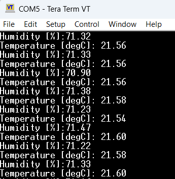
- Monitor Sensor Data → Open UART Serial Monitor.
- Test I²C Communication → Sensor readings appear in real-time. Open Tera Term or similar Serial Monitor.
6. Hands-On Lab Recap
You learned:
- How to configure I2C peripheral in CubeMX.
- How to read data from a sensor using the available driver.
- How to send sensor data via UART for monitoring.
- Optional techniques: interrupts and DMA for efficient data handling.
This opens the door for sensor-based applications, like environmental monitoring or IoT projects.
7. Common Issues & Fixes
| Issue | Cause | Solution |
|---|---|---|
| I2C device not detected | Wrong SCL/SDA pins | Verify CubeMX pinout |
| HAL timeout | Incorrect sensor address or timing | Check sensor datasheet and I2C timing |
| Data corrupted | Pull-up resistors missing | Add external pull-ups on SCL and SDA or enable the internal pull-up |
| Compilation error | HAL_I2C functions missing | Regenerate CubeMX code |
8. What’s Next
In Episode 8, we’ll explore SPI communication:
- Connect STM32 to OLED displays or external EEPROMs.
- Read and write data using HAL.
- Hands-on lab: Display sensor readings on OLED.