ESP32 Tutorial: ADC Tutorial | Reading Basic Analog Input
Abstract
The Analog-to-Digital Converter (ADC) is a critical component that allows a microcontroller, which operates solely on digital logic (HIGH/LOW), to interpret continuous electrical signals from the physical world. This tutorial explains the ESP32’s powerful 12-bit ADC hardware and demonstrates how to use the standard Arduino function, analogRead(), to accurately measure an analog voltage, such as the output from a potentiometer or an analog sensor.
1. Introduction
Digital inputs can only tell us if a signal is ON (HIGH) or OFF (LOW). However, many common sensors, such as temperature sensors (thermistor), light sensors (photoresistor), and potentiometers, produce a smoothly varying voltage proportional to the physical property they are measuring.
The ESP32’s built-in ADC translates this continuous voltage (which can range from 0V to 3.3V) into a whole number, which the CPU can process.
ESP32 ADC Features
- Resolution: The ESP32 ADC has a 12-bit resolution. This means the maximum analog voltage is mapped to an integer value between 0 and 212−1, or 0 to 4095.
- Channels: The ESP32 contains two ADC units:
- ADC1: Has 8 channels, typically safer to use.
- ADC2: Has 10 channels, but cannot be used when the Wi-Fi modem is active. For most IoT applications, using ADC1 pins is recommended to avoid conflicts.
- Voltage: All ESP32 GPIO pins, including ADC inputs, operate at 3V logic. The default measurement voltage range is configurable, but the maximum input voltage to the pin must never exceed 3.3V.
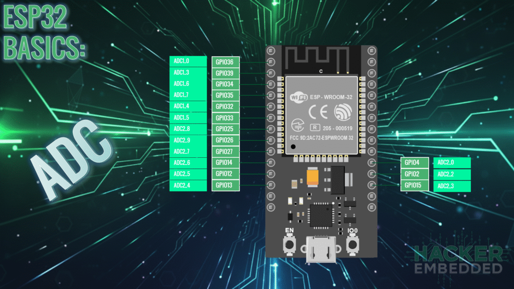
Pinout for the 30-pin evaluation board:
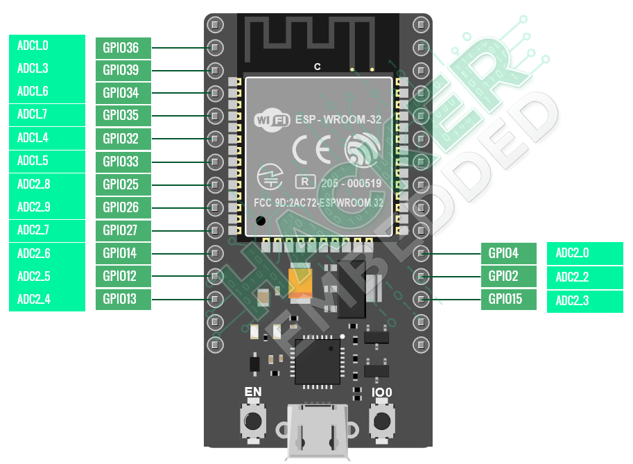
Recommended ADC1 Pins
The following pins are part of the ADC1 unit and are generally safe to use for analog input in Wi-Fi projects:
- GPIO 32 (ADC1_CH4)
- GPIO 33 (ADC1_CH5)
- GPIO 34 (ADC1_CH6) – Input Only
- GPIO 35 (ADC1_CH7) – Input Only
2. Core Function: analogRead()
Reading an analog value on the ESP32 using the Arduino Core is as simple as calling the standard analogRead() function.
2.1 Using analogRead(pin)
int reading = analogRead(pin);
- pin: The GPIO pin number connected to the analog signal.
- Returns: An integer value from 0 (0V) to 4095 (3.3V, depending on attenuation).
2.2 Optional: Setting Attenuation (For Full Range)
By default, the ESP32’s ADC may only read up to about 1.1V for better noise immunity. To read the full 0V to 3.3V range, you need to set the ADC attenuation in the setup() function:
void setup() {
// Set the ADC to read the full range (0V to 3.3V)
analogSetAttenuation(ADC_11db);
// … other setup
}
For basic reading, the simple analogRead() function will work, but for accurate voltage measurement across the entire 3.3V range, the attenuation setting is necessary.
3. Hands-On Lab: Reading a Potentiometer
This lab demonstrates how to read a variable voltage from a potentiometer and display the raw 12-bit value in the Serial Monitor.
Wiring
- Connect the Side Pin 1 of the potentiometer to GND on the ESP32.
- Connect the Side Pin 3 of the potentiometer to 3.3V on the ESP32.
- Connect the Wiper Pin 2 (Middle Pin) of the potentiometer to GPIO 32 on the ESP32.
ESP32 ADC Read Code Example
#define POT_PIN 32 // ADC1 Channel 4
void setup() {
// Initialize Serial communication
Serial.begin(115200);
// Optional: Set attenuation for full 0-3.3V reading range
analogSetAttenuation(ADC_11db);
}
void loop() {
// Read the analog value from the potentiometer pin
int rawValue = analogRead(POT_PIN);
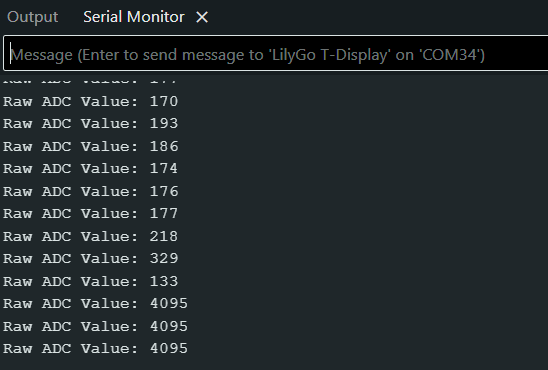
// Print the raw 12-bit value to the Serial Monitor
Serial.print("Raw ADC Value: ");
Serial.println(rawValue);
// Wait a short time before the next reading
delay(100);
}
Execution Steps
- Upload the sketch to your ESP32 board.
- Open the Serial Monitor and ensure the baud rate is set to 115200.
- Rotate the knob on the potentiometer:
- Turning the knob fully one direction should show a reading near 0.
- Turning the knob fully the opposite direction should show a reading near 4095.
- The values in between will change smoothly as you turn the knob.
4. Lab Recap
You’ve learned the fundamental steps for reading analog input on your ESP32:
- The ESP32 uses a 12-bit ADC, resulting in a raw reading range of 0 to 4095.
- The function analogRead(pin) is used to fetch the raw ADC value.
- You must be aware of the ADC2/Wi-Fi conflict and preferentially use pins associated with ADC1 (such as GPIO 32, 33, 34, 35).
- The optional function analogSetAttenuation(ADC_11db) is necessary to configure the ADC to read the full 0V to 3.3V range of your sensors.
- Serial communication is used to monitor and debug the raw analog data being read by the microcontroller.

