Arduino Tutorial: KY-008 Laser Transmitter Module
Abstract
Learn how to use the KY-008 Laser Transmitter Module with Arduino. This module contains a small laser diode that emits a focused beam of visible red light. This tutorial focuses on configuring a digital output pin to act as a simple ON/OFF switch for the laser, enabling basic line-of-sight communication or alignment projects.
1. Introduction
The KY-008 is fundamentally a high-power LED operating in the laser range. Its key feature is that it produces a highly collimated (focused) beam of light, making it visible over long distances and useful for precise targeting.
⚠️ CAUTION: Never look directly into the laser beam or point it at people or animals, as it can cause eye damage.
In this episode, you’ll learn:
- The difference between a laser diode and a standard LED.
- How to safely wire the module as a digital output.
- How to use digitalWrite() to turn the laser ON and OFF.
- How to implement a basic Morse code signaling
This project introduces a high-impact visual output controlled by simple digital logic.
2. Prerequisites
Make sure you have:
- An Arduino Uno or compatible board.
- One KY-008 Laser Transmitter Module.
- Jumper Wires.
- Arduino IDE
3. Wiring and Setup for Arduino
The KY-008 module requires a simple digital output pin for control.
Step 1 – Identify Pins
The module typically has three pins: Signal (S or OUT), VCC (+), and Ground (− or GND).
Step 2 – Connect the Module
Wire the module to the Arduino as follows:
- Connect the – / GND pin of the KY-008 to the GND pin on the Arduino.
- Connect the + / VCC pin of the KY-008 to the 5V pin on the Arduino.
- Connect the S / Signal pin of the KY-008 to Arduino Digital Pin 8.
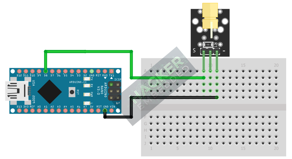
This image was created with Fritzing
Step 3 – Initialize Pin Mode
In the setup() function of your code, set the signal pin as an OUTPUT:
pinMode(8, OUTPUT);
4. Writing Laser Control Code (Morse Code Example)
We will use the laser to transmit the letter ‘S’ in Morse code (dot-dot-dot, or short pulses) and the letter ‘O’ (dash-dash-dash, or long pulses), separated by a pause.
Open main.ino and implement the following code.
					const int LASER_PIN = 8;

// Timing constants for Morse Code
const int DOT_TIME = 100; // 100 milliseconds for a 'dot'
const int DASH_TIME = DOT_TIME * 3; // 300 milliseconds for a 'dash'
const int ELEMENT_GAP = DOT_TIME; // Gap between dots and dashes in a letter
const int LETTER_GAP = DOT_TIME * 3; // Gap between letters

// Function to send a short pulse (DOT)
void dot() {
  digitalWrite(LASER_PIN, HIGH); // Laser ON
  delay(DOT_TIME);
  digitalWrite(LASER_PIN, LOW); // Laser OFF
  delay(ELEMENT_GAP);
}

// Function to send a long pulse (DASH)
void dash() {
  digitalWrite(LASER_PIN, HIGH); // Laser ON
  delay(DASH_TIME);
  digitalWrite(LASER_PIN, LOW); // Laser OFF
  delay(ELEMENT_GAP);
}


void setup() {
  pinMode(LASER_PIN, OUTPUT);
  Serial.begin(9600);
  Serial.println("KY-008 Laser Morse Code Transmitter Ready!");
  Serial.println("Transmitting SOS...");
}

void loop() {
  // Transmit 'S' (dot dot dot)
  dot(); dot(); dot();
  delay(LETTER_GAP);

  // Transmit 'O' (dash dash dash)
  dash(); dash(); dash();
  delay(LETTER_GAP);

  // Transmit 'S' (dot dot dot)
  dot(); dot(); dot();
  delay(LETTER_GAP * 3); // Long pause between SOS sequences
}
Code Explanation
- digitalWrite(LASER_PIN, HIGH): Sends 5V to the module’s signal pin, turning the laser diode ON.
- digitalWrite(LASER_PIN, LOW): Cuts the voltage, turning the laser diode OFF.
- Timing Functions: The dot() and dash() functions encapsulate the precise timing required for Morse code signaling, allowing the laser to transmit data visually.
5. Uploading and Running the Project
Step 1 – Build & Upload
Complete the standard build and upload process.
Step 2 – Test
- Direct the laser onto a non-reflective, matte surface (like a piece of paper or a wall) across the room.
- Observe the laser spot: it should flash in the dot-dot-dot, dash-dash-dash, dot-dot-dot pattern (SOS) with appropriate gaps, repeating indefinitely.
6. Hands-On Lab Recap
You’ve learned:
- How to use a laser diode module as a digital output.
- How to safely handle the KY-008.
- How to implement timed pulses using delay() for visual signaling.
This concludes the comprehensive series on fundamental KY-series modules, providing you with a complete toolkit for basic electronic projects.
7. Common Issues & Fixes
| Issue | Cause | Solution |
|---|---|---|
| Laser is always ON or never turns ON. | Wiring Error or Signal pin misconfiguration. | Check that 5V and GND are correct. Ensure pinMode(LASER_PIN, OUTPUT); is in setup(). |
| Laser is very dim. | Power supply issue (Arduino current limit). | The KY-008 usually draws little current. Ensure the 5V pin is used, not a 3.3V pin. |
| The laser beam is not visible. | Environmental factors. | Ensure the test surface is non-reflective and the room is not too brightly lit, as this can wash out the red laser light. |

