
Arduino Tutorial: KY-012 Active Buzzer Module
Abstract
Learn how to use the KY-012 Active Buzzer Module with Arduino. This module contains an internal oscillator, allowing it to generate a loud, fixed-frequency tone simply by applying a HIGH digital signal. This tutorial focuses on using digital output pins to create timed alert sounds and simple beeping sequences.
1. Introduction
The KY-012 is an Active Buzzer, meaning it functions as a simple digital output device. Unlike a passive buzzer (which requires the tone() function and a specific frequency), the active buzzer only needs 5V (a HIGH signal) to instantly generate its fixed-frequency sound. This makes it ideal for immediate, simple alerts and alarm systems.
In this episode, you’ll learn:
- The difference between Active and Passive buzzers.
- How to safely wire the module as a digital output device.
- How to use digitalWrite() to turn the sound ON and OFF.
- How to create a simple alarm pulse using delays.
This project adds the capability of audible feedback to your Arduino projects.
2. Prerequisites
Make sure you have:
- An Arduino Uno or compatible board.
- One KY-012 Active Buzzer Module.
- Jumper Wires.
- Arduino IDE
3. Wiring and Setup for Arduino
The KY-012 module has three pins and requires a digital signal to activate.
Step 1 – Identify Pins
The module typically has three pins: Signal (S or OUT), VCC (+), and Ground (− or GND).
Step 2 – Connect the Module
Wire the module to the Arduino as follows:
- Connect the – / GND pin of the KY-012 to the GND pin on the Arduino.
- Connect the + / VCC pin of the KY-012 to the 5V pin on the Arduino.
- Connect the S / Signal pin of the KY-012 to Arduino Digital Pin 10.
Note: The VCC pin is often connected to the Arduino’s 5V to power the circuit, while the S pin is used to gate the power to the buzzer element itself via an integrated transistor, or vice-versa, depending on the module. For the KY-012, setting the S pin HIGH typically activates the buzzer.
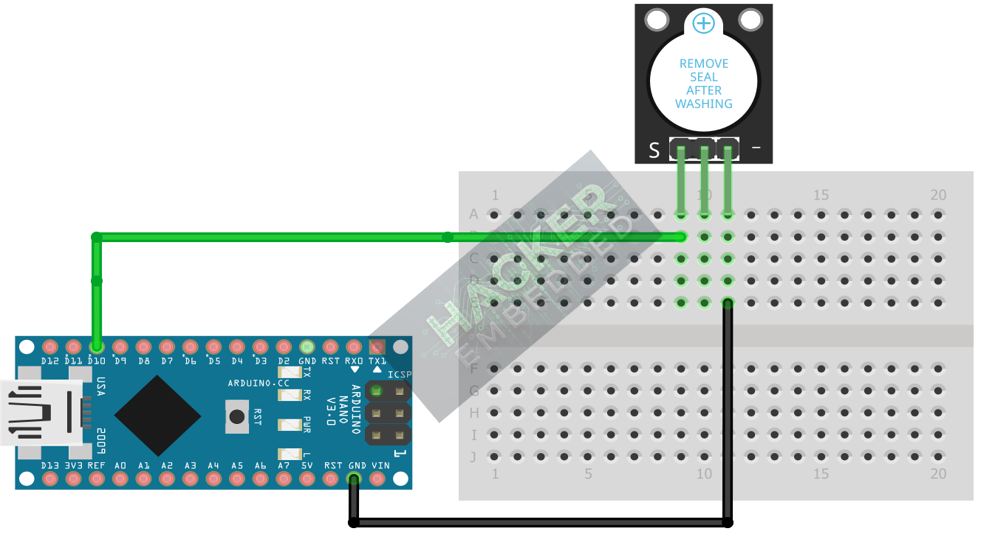
This image was created with Fritzing
Step 3 – Initialize Pin Mode
The signal pin must be initialized as an OUTPUT in the setup() function:
pinMode(10, OUTPUT);
4. Writing Simple Alert Code
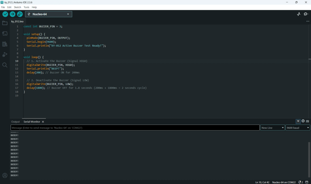
Open main.ino and implement the following code. This code will generate a short beep every two seconds.
					const int BUZZER_PIN = 10;

void setup() {
  pinMode(BUZZER_PIN, OUTPUT);
  Serial.begin(9600);
  Serial.println("KY-012 Active Buzzer Test Ready!");
}

void loop() {
  // 1. Activate the Buzzer (Signal HIGH)
  digitalWrite(BUZZER_PIN, HIGH);
  Serial.println("BEEP!");
  delay(200); // Buzzer ON for 200ms

  // 2. Deactivate the Buzzer (Signal LOW)
  digitalWrite(BUZZER_PIN, LOW);
  delay(1800); // Buzzer OFF for 1.8 seconds (200ms + 1800ms = 2 seconds cycle)
}
Code Explanation
- digitalWrite(BUZZER_PIN, HIGH): Sends 5V to the signal line, triggering the internal oscillator within the active buzzer and producing the fixed-frequency tone.
- digitalWrite(BUZZER_PIN, LOW): Stops the 5V signal, effectively silencing the buzzer.
- delay(): Used to control the duration of the sound and the silent period between beeps.
5. Creating a Pulse Sequence
For alarm systems, you often need a sequence of pulses. This can be easily implemented using a function and loops.
					// Function to generate a sequence of short beeps
void pulseSequence(int count, int duration_ms, int pause_ms) {
  for (int i = 0; i < count; i++) {
    digitalWrite(BUZZER_PIN, HIGH);
    delay(duration_ms);
    digitalWrite(BUZZER_PIN, LOW);
    delay(pause_ms);
  }
}

void loop() {

   // Generate three quick 50ms beeps, separated by 50ms pauses
  pulseSequence(3, 50, 50);

  // Pause for 5 seconds before repeating
  delay(5000);

}
6. Uploading and Testing the Project
Step 1 – Build
Click the Verify button (checkmark icon) in the Arduino IDE to compile the sketch.
Step 2 – Upload
- Connect your Arduino board via USB.
- Select the correct board and COM port.
- Click the Upload (arrow icon) button.
Step 3 – Test
- If you ran the code from Section 4, the buzzer should produce a 200ms beep every two seconds.
- If you ran the code from Section 5, the buzzer should produce a triple, rapid beeping sound every five seconds.
7. Hands-On Lab Recap
You’ve learned:
- The simple ON/OFF activation of an Active Buzzer using the internal oscillator.
- How to configure a Digital pin as output for sound alerts.
- How to use digitalWrite() and delay() to control the duration of the tone.
This concludes our series on basic digital output and feedback devices.
8. Common Issues & Fixes
| Issue | Cause | Solution |
|---|---|---|
| Buzzer is always ON or always OFF. | Wiring error or using the wrong pin mode. | Ensure the signal pin is set to OUTPUT and that VCC is connected to 5V and GND to GND. Try reversing the logic (e.g., if HIGH doesn't work, ensure LOW isn't activating it). |
| Buzzer is quiet or clicks instead of beeping. | Insufficient current or faulty module. | Check wiring for loose connections. The Active Buzzer should be loud; if not, the module may be defective or underpowered (though Arduino's 5V is usually sufficient). |
| Code compiles but no sound. | Pin assignment error. | Ensure the BUZZER_PIN variable matches the physical wire location on the Arduino. |

