Arduino Tutorial: KY-018 Photoresistor
Abstract
Learn how to read analog input from the KY-018 Photoresistor Module using an Arduino Uno and display the raw light intensity values on the Serial Monitor. This fundamental project establishes how to interface with analog sensors, a crucial skill for interactive projects.
1. Introduction
Following an initial “Hello World” style project, it’s time to read input from an analog sensor—a fundamental skill for creating projects that react to the environment. The KY-018 module is a simple light sensor that utilizes a Photoresistor or Light-Dependent Resistor (LDR).
In this episode, you’ll learn:
- How the KY-018 module works as a voltage divider.
- How to wire the analog sensor to an Arduino.
- How to use the analogRead() function to read the light intensity.
- How to output the raw sensor data to the Serial Monitor.
This project will allow your Arduino to sense ambient light, laying the foundation for automated lighting or light-measurement applications.
2. Prerequisites
Make sure you have:
- An Arduino Uno board (or similar Arduino board).
- A KY-018 Photoresistor Module.
- Jumper wires for connections.
- Arduino IDE
3. Wiring and Setup for Arduino
The KY-018 module contains a Light-Dependent Resistor (LDR) and a fixed 10 kΩ resistor arranged in a voltage divider circuit.
- LDR Principle: The LDR’s resistance decreases as the ambient light intensity increases.
- Analog Output: The module’s output is an analog voltage that changes continuously with light intensity.
- In bright light, the LDR’s resistance is low, resulting in a higher output voltage (a high analog value).
- In the dark, the LDR’s resistance is high, resulting in a lower output voltage (a low analog value).
Pinout and Wiring
The KY-018 has three pins:
KY-018 Pin | Function | Arduino Connection |
– | Ground (GND) | GND |
(middle) | Power (VCC) | 5V |
S | Signal (Analog Out) | Analog Pin (e.g., A0) |
Connect the module to your Arduino Uno as follows:
- KY-018 Pin (-) to Arduino GND.
- KY-018 Pin (middle) to Arduino 5V.
KY-018 Pin (S) to Arduino Analog Pin A0.
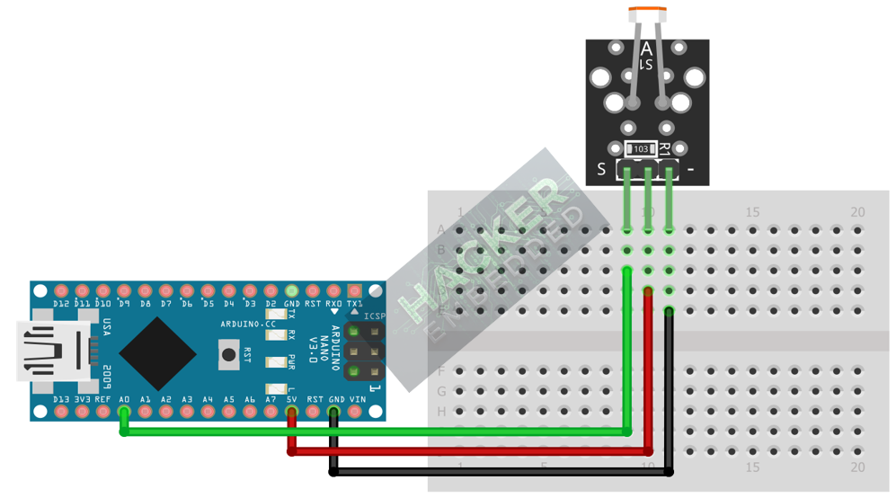
This image was created with Fritzing
4. Writing the Light Intensity Meter Code
The goal is to read the raw analog value from pin A0, which ranges from 0 (dark) to 1023 (bright) on a standard 10-bit Arduino ADC.
Open the Arduino IDE and copy the following sketch:
					// KY-018 Photoresistor Module Example Code
// Reads the raw analog light intensity and prints it to the Serial Monitor

int sensorPin = A0;    // Select the analog input pin for the photoresistor

void setup() {
  // Initialize serial communication at 9600 bits per second
  Serial.begin(9600);
  Serial.println("KY-018 Photoresistor Test");
}

void loop() {
  // Read the raw analog value from the sensor (0 to 1023)
  int sensorValue = analogRead(sensorPin);

  // Print the value to the Serial Monitor
  Serial.print("Light Intensity (Raw ADC): ");
  Serial.println(sensorValue);

  // Wait 500 milliseconds before reading again
  delay(500);
}
Code Explanation
- int sensorPin = A0;: Declares the connection pin for the sensor.
- begin(9600);: Initializes the serial port for communication.
- int sensorValue = analogRead(sensorPin);: Reads the analog voltage on pin A0 and converts it into a digital value between 0 and 1023.
- println(sensorValue);: Sends the light intensity value to your computer’s Serial Monitor.
5. Uploading and Running the Project
Step 1 – Upload
- In the Arduino IDE, select the correct Board (e.g., Arduino Uno) and Port.
- Click the Upload button (right arrow icon).
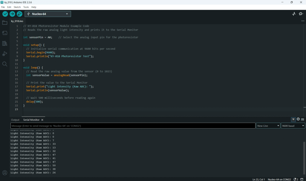
Step 2 – Test
- Once the code is uploaded, open the Serial Monitor (magnifying glass icon).
- The raw sensor value (0-1023) will be printed every 500ms.
- Test the light response:
- Cover the LDR with your finger: the value should drop low (close to 0).
- Shine a bright light on the LDR: the value should rise high (close to 1023).
6. Hands-On Lab Recap
You’ve successfully learned how to interface an Arduino with an analog light sensor! You’ve learned:
- How to use the KY-018 Photoresistor Module.
- How to wire the VCC, GND, and Signal (S)
- How to read analog sensor values with analogRead().
- How to output data to the Serial Monitor.
This adds environmental sensing to your Arduino projects, preparing you for logic-based control in the next tutorials.
7. Common Issues & Fixes
| Issue | Cause | Solution |
|---|---|---|
| No values in Serial Monitor | Wrong Baud Rate selected in the monitor. | Ensure the Serial Monitor is set to 9600 baud. |
| Readings are stuck at 0 or 1023 | Wiring or power issue. | Verify the VCC, GND, and Signal pins are connected securely and correctly (5V, GND, A0). |
| Readings fluctuate rapidly | Sensor noise or unstable lighting. | Implement software filtering (like averaging multiple readings) or ensure stable light conditions. |

