Arduino Tutorial: KY-019 5V Relay Module
Abstract
Learn how to use the KY-019 5V Relay Module with Arduino. A relay is an electrically operated switch that allows a low-power digital circuit (like an Arduino) to control a high-power AC or DC circuit (like a lamp, motor, or appliance). This tutorial focuses on configuring a digital output pin to activate the relay’s coil, effectively using the Arduino to switch large loads.
1. Introduction
The KY-019 module contains a 5V electromagnetic relay, which is essentially a mechanical switch actuated by an electromagnet. The core principle is isolation: the Arduino controls the low-voltage side (coil), and the relay’s contacts switch the high-voltage side (load) without any electrical connection between the two circuits.
⚠️ WARNING: Relays are typically used to switch high voltages (e.g., 120V or 240V AC). DO NOT attempt to wire the high-voltage side of the relay unless you are properly trained and take all necessary safety precautions. For this tutorial, we will only demonstrate switching a low-voltage DC load (like a separate LED).
In this episode, you’ll learn:
- The principle of electromagnetic switching and isolation.
- The difference between Normally Open (NO) and Normally Closed (NC)
- How to safely wire the relay module to the Arduino.
- How to use digitalWrite() to control the load circuit.
This project enables your Arduino to control powerful, real-world devices.
2. Prerequisites
Make sure you have:
- An Arduino Uno or compatible board.
- One KY-019 5V Relay Module.
- One separate low-voltage DC load for safe testing (e.g., a 9V battery and a separate LED with a current-limiting resistor, or a small DC motor).
- Jumper Wires.
- Arduino IDE
3. Wiring and Setup for Arduino
The KY-019 module requires a digital output pin for control and a separate power source for the load.
Step 1 – Identify Pins
The module has two sections:
- Low-Voltage Side (Control): S (Signal/Input), VCC (5V), and GND (Control Ground).
- High-Voltage Side (Load): COM (Common), NO (Normally Open), and NC (Normally Closed).
Step 2 – Connect the Control Side (Arduino)
Wire the control side to the Arduino:
- Connect the GND pin of the KY-019 to the GND pin on the Arduino.
- Connect the VCC pin of the KY-019 to the 5V pin on the Arduino.
- Connect the S pin of the KY-019 to Arduino Digital Pin 8.
Step 3 – Connect the Load Side (External Power)
We will use the NO (Normally Open) configuration, meaning the load is OFF when the relay is de-energized and ON when the relay is energized.
- Connect the positive (+) terminal of your external DC power source (e.g., 9V battery) to the COM pin of the relay.
- Connect the NO pin of the relay to the positive side of your DC load (e.g., the resistor/LED assembly).
- Connect the negative (−) terminal of the DC load back to the negative (−) terminal of the external power source.
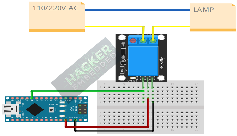
This image was created with Fritzing
Step 4 – Initialize Pin Mode
In the setup() function of your code, set the signal pin as an OUTPUT:
pinMode(8, OUTPUT);
4. Writing Relay Control Code
Relay modules often use Active LOW logic, meaning sending a LOW signal (GND) to the input pin activates the coil and switches the contacts. We will confirm this behavior in the code.
Open main.ino and implement the following code.
					const int RELAY_PIN = 8;
const int CYCLE_TIME = 2000; // 2 seconds

void setup() {
  pinMode(RELAY_PIN, OUTPUT);
  Serial.begin(9600);
  Serial.println("KY-019 Relay Test Ready!");

  // Initialize the relay to the OFF state (Sending HIGH signal to prevent switching)
  digitalWrite(RELAY_PIN, HIGH);
}

void loop() {
  Serial.println("Relay ON (Active LOW)...");
  digitalWrite(RELAY_PIN, LOW); // Send LOW to signal pin to ACTIVATE coil
  delay(CYCLE_TIME);

  Serial.println("Relay OFF (Active HIGH)...");
  digitalWrite(RELAY_PIN, HIGH); // Send HIGH to signal pin to DEACTIVATE coil
  delay(CYCLE_TIME);
}
Code Explanation
- Active LOW: The code assumes the common Active LOW configuration where LOW activates the coil. When activated, you should hear a click from the relay, and the external load should turn ON (since it’s wired to NO).
- digitalWrite(RELAY_PIN, LOW): Energizes the relay coil, switching the mechanical contacts from NC to NO, powering the load.
- digitalWrite(RELAY_PIN, HIGH): De-energizes the coil, switching the mechanical contacts back from NO to NC, turning the load OFF.
5. Uploading and Running the Project
Step 1 – Build & Upload
Complete the standard build and upload process.
Step 2 – Test
- Listen for a distinct mechanical clicking sound every two seconds.
- Observe the external DC load: it should turn ON for 2s and turn OFF for 2s, cycling indefinitely.
- Observe the onboard indicator LED: it should light up when the relay is active (coil is energized).
6. Hands-On Lab Recap
You’ve learned:
- The essential role of a relay for low-voltage control of high-voltage loads.
- The difference between the control circuit and the load circuit (isolation).
- How to use the NO and NC contacts.
- How to write digital output code to activate the relay.
This concludes the comprehensive series on fundamental KY-series modules, providing you with a complete toolkit for basic electronic projects.
7. Common Issues & Fixes
| Issue | Cause | Solution |
|---|---|---|
| Arduino works, but no clicking sound or load control. | Control side wiring is wrong (VCC/GND/S) or relay is faulty. | Double-check the VCC (5V) and GND pins are connected to the Arduino. |
| Clicking sound is heard, but the external load never turns ON. | Load side wiring is wrong or load circuit is not receiving power. | Check the connections between the external power supply, COM, NO (or NC), and the load. Ensure the external power source is working. |
| Relay turns ON when the code says OFF. | Logic is reversed (Active HIGH instead of Active LOW). | Change the code logic: use HIGH to activate and LOW to deactivate. Also, ensure your load is wired to the desired contact (NO or NC). |

