Arduino Tutorial: KY-021 Mini Magnetic Reed Switch Module
Abstract
Learn how to use the KY-021 Mini Magnetic Reed Switch Module with Arduino. This module contains a magnetically actuated digital switch that closes its internal contacts when a nearby magnetic field is detected. This tutorial focuses on configuring Arduino digital input pins to detect the presence or absence of a magnet, creating a simple, reliable proximity sensor.
1. Introduction
The KY-021 utilizes a reed switch, a small glass envelope containing two ferrous reeds. In the absence of a magnetic field, the reeds are apart (open circuit). When a magnet is brought close, the reeds are pulled together, closing the circuit. The module also includes a series resistor and often an indicator LED.
In this episode, you’ll learn:
- The simple reed switch principle and its applications (e.g., door alarms).
- How to safely wire the module as a digital input.
- How to read the switch state using digitalRead().
- How to use the input to trigger an ON/OFF state change (e.g., controlling a safety light).
This project adds a crucial form of non-contact proximity sensing to your Arduino repertoire.
2. Prerequisites
Make sure you have:
- An Arduino Uno or compatible board.
- One KY-021 Mini Magnetic Reed Switch Module.
- One small magnet (often included).
- Jumper Wires.
- Arduino IDE
3. Wiring and Setup for Arduino
The KY-021 module has three pins and requires a digital input pin.
Step 1 – Identify Pins
The module typically has three pins: Signal (S or OUT), VCC (+), and Ground (− or GND).
Step 2 – Connect the Module
Wire the module to the Arduino as follows. The module often has an internal pull-up resistor, causing the signal to go LOW when the switch closes (magnet is present).
- Connect the – / GND pin of the KY-021 to the GND pin on the Arduino.
- Connect the + / VCC pin of the KY-021 to the 5V pin on the Arduino.
- Connect the S / Signal pin of the KY-021 to Arduino Digital Pin 7.
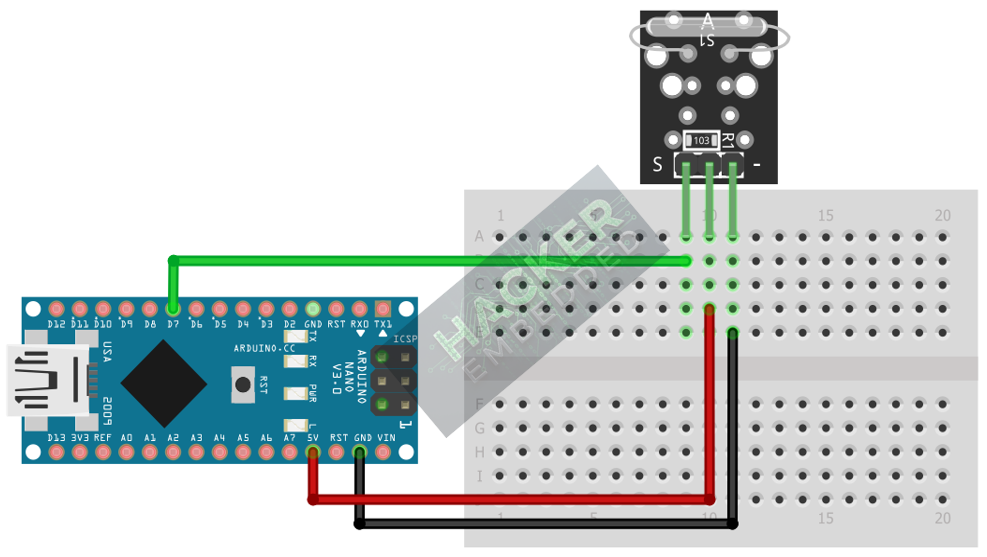
This image was created with Fritzing
Step 3 – Initialize Pin Mode
In the setup() function of your code, set the signal pin as a standard input:
pinMode(7, INPUT);
We will use the on-board LED (Pin 13) as our output indicator, set as OUTPUT.
4. Writing Magnetic Detection Code
Open main.ino and implement the following code. This code will turn the built-in LED (Pin 13) ON when a magnet is detected (switch is closed, resulting in a LOW signal).
					const int REED_SWITCH_PIN = 7;
const int LED_PIN = 13; // Built-in LED

void setup() {
  pinMode(LED_PIN, OUTPUT);
  // Set the sensor pin as input
  pinMode(REED_SWITCH_PIN, INPUT);

  Serial.begin(9600);
  Serial.println("KY-021 Reed Switch Test Ready!");
}

void loop() {
  // Read sensor state (LOW indicates switch is closed / magnet detected)
  int sensorState = digitalRead(REED_SWITCH_PIN);

  if(sensorState == LOW) // Check if magnet is present
  {
    digitalWrite(LED_PIN, HIGH); // Turn LED ON (Alert State)
    Serial.println("MAGNET DETECTED! (Door Open)");
  }
  else
  {
    digitalWrite(LED_PIN, LOW); // Turn LED OFF
    Serial.println("Status: Clear. (Door Closed)");
  }

  // A small delay to prevent overwhelming the serial monitor
  delay(50);
}
Code Explanation
- The if statement checks for an Active LOW signal, which occurs when the magnet pulls the reed contacts together, connecting the signal pin to GND.
- Sustained Output: The LED remains ON as long as the magnet is close enough to keep the switch closed.
5. Handling Switch Polling vs. Interruption
The reed switch has minimal bounce, making the continuous polling method (checking the pin state in loop()) highly effective.
Edge-Triggered Toggle
If you wanted the magnet’s detection to toggle the LED state (e.g., magnet presence turns the light ON, magnet removal turns it OFF, requiring both edges to trigger a change), you would use the more complex state change detection logic previously introduced in the KY-004 tutorial.
For simple security or proximity sensing, the continuous polling method shown in Section 4 is usually preferred.
6. Uploading and Running the Project
Step 1 – Build
Click the Verify button (checkmark icon) in the Arduino IDE to compile the sketch.
Step 2 – Upload
- Connect your Arduino board via USB.
- Select the correct board and COM port.
- Click the Upload (arrow icon) button.
Step 3 – Test
- Open the Serial Monitor (Tools > Serial Monitor).
- Keep the magnet far away: the LED should be OFF, and the monitor should show “Status: Clear.”
- Bring the magnet close to the glass tube on the module: the LED should turn ON, and the monitor should show “MAGNET DETECTED!” continuously until the magnet is removed.
7. Hands-On Lab Recap
You’ve learned:
- How the KY-021 reed switch uses a magnetic field to close a circuit.
- How to configure Digital pins as input for this type of sustained switch.
- The expected Active LOW behavior when the switch is activated.
- How to create a simple, non-contact proximity sensor.
This concludes your knowledge of simple digital input switches.
8. Common Issues & Fixes
| Issue | Cause | Solution |
|---|---|---|
| LED is always ON when the magnet is far away. | Logic Inversion required. | Try reversing the logic condition: change LOW to HIGH in the if statement. |
| LED never turns ON when the magnet is near. | Wiring error (VCC/GND reversed or signal pin wrong). | Double-check 5V and GND. Ensure the REED_SWITCH_PIN matches the wire on the Arduino. |
| Switch only works at certain orientations. | Magnetic Pole orientation sensitivity. | Try flipping the magnet over or rotating it. Reed switches often respond best to one specific magnetic pole orientation. |

