Arduino Tutorial: KY-026 Flame Sensor Module
Abstract
Learn how to use the KY-026 Flame Sensor Module with Arduino. This module is an essential safety component that detects infrared (IR) light emitted by a flame. It provides both a digital ON/OFF signal (D0) for simple flame presence and a raw analog value (A0) indicating the IR light intensity. This tutorial focuses on using both inputs and calibrating the digital trigger using the onboard potentiometer.
1. Introduction
The KY-026 module uses an IR receiver specifically tuned to the 760nm to 1100nm wavelength range, which is strongly emitted by fire/flames.
- Analog Output (A0): Provides a continuous voltage proportional to the intensity of the detected IR light. The voltage is typically low when light intensity is high (close to a flame).
- Digital Output (D0): An onboard comparator uses the analog signal to provide a simple, adjustable HIGH/LOW switch. The threshold for triggering the switch is set by the potentiometer, allowing you to set the sensitivity.
In this episode, you’ll learn:
- The principle of infrared flame detection.
- How to use the analog output (A0) to measure IR intensity/proximity to the flame.
- How to use the digital output (D0) for a reliable, threshold-based alarm.
- How to use the onboard potentiometer to set the detection sensitivity/range.
This project enables the Arduino to perform critical safety monitoring.
2. Prerequisites
Make sure you have:
- An Arduino Uno or compatible board.
- One KY-026 Flame Sensor Module.
- Jumper Wires.
- Arduino IDE
- A safe, small flame source for testing (e.g., a candle or lighter).
⚠️ SAFETY NOTE: Always conduct flame testing under strict supervision in a safe, controlled environment, away from flammable materials.
3. Wiring and Setup for Arduino
The KY-026 module has four pins and requires both digital and analog input pins.
Step 1 – Identify Pins
The module typically has four pins: A0 (Analog Output), D0 (Digital Output), VCC (+), and GND (− or GND).
Step 2 – Connect the Module
Wire the module to the Arduino as follows:
- Connect the GND pin of the KY-026 to the GND pin on the Arduino.
- Connect the VCC pin of the KY-026 to the 5V pin on the Arduino.
- Connect the D0 pin of the KY-026 to Arduino Digital Pin 7 (Digital Input).
- Connect the A0 pin of the KY-026 to Arduino Analog Pin A0 (Analog Input).
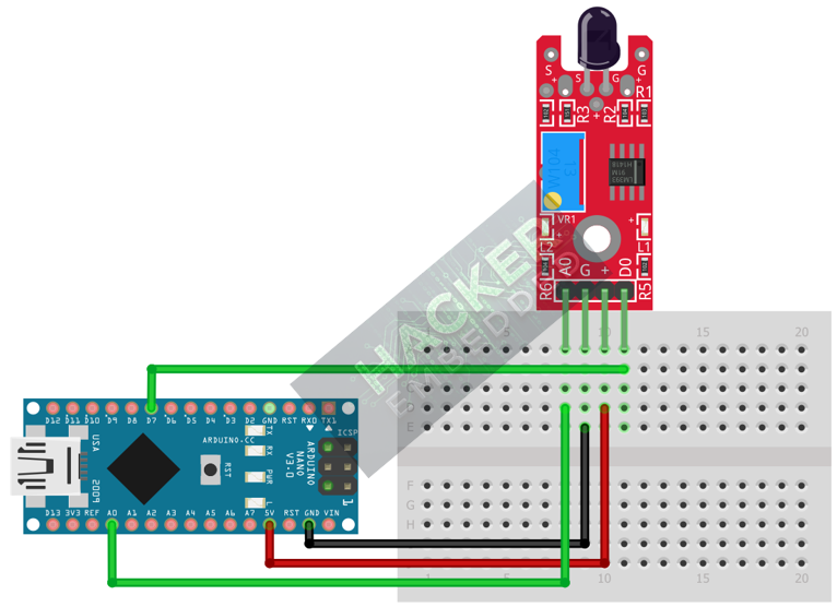
This image was created with Fritzing
Step 3 – Initialize Pin Modes
pinMode(7, INPUT); // D0 pin for digital ON/OFF detection
We will use the on-board LED (Pin 13) to reflect the digital trigger state.
4. Writing Dual-Mode Flame Sensing Code
We will monitor the analog output for IR intensity and use the digital output to trigger a simple alarm based on the preset sensitivity.
Open main.ino and implement the following code.
const int DIGITAL_PIN = 7; // D0 Output
const int ANALOG_PIN = A0; // A0 Output
const int LED_PIN = 13; // Built-in LED
void setup() {
pinMode(LED_PIN, OUTPUT);
pinMode(DIGITAL_PIN, INPUT);
Serial.begin(9600);
Serial.println("KY-026 Flame Sensor Ready! Calibrate Digital Threshold.");
}
void loop() {
// 1. Read Analog State (A0)
// Raw 0-1023 value. Value is typically HIGH when far from a flame (low IR).
// Value drops LOW when IR intensity increases (near a flame).
int analogValue = analogRead(ANALOG_PIN);
// 2. Read Digital State (D0)
// We assume HIGH means flame detected (Active HIGH logic).
// NOTE: Some modules are Active LOW. Test yours and adjust the code below.
int digitalState = digitalRead(DIGITAL_PIN);
// Control LED based on Digital Output (Alarm Trigger)
// Assuming Active HIGH logic (LOW when clear, HIGH when triggered)
if (digitalState == HIGH) {
digitalWrite(LED_PIN, HIGH); // Turn LED ON (FLAME DETECTED)
} else {
digitalWrite(LED_PIN, LOW); // Turn LED OFF
}
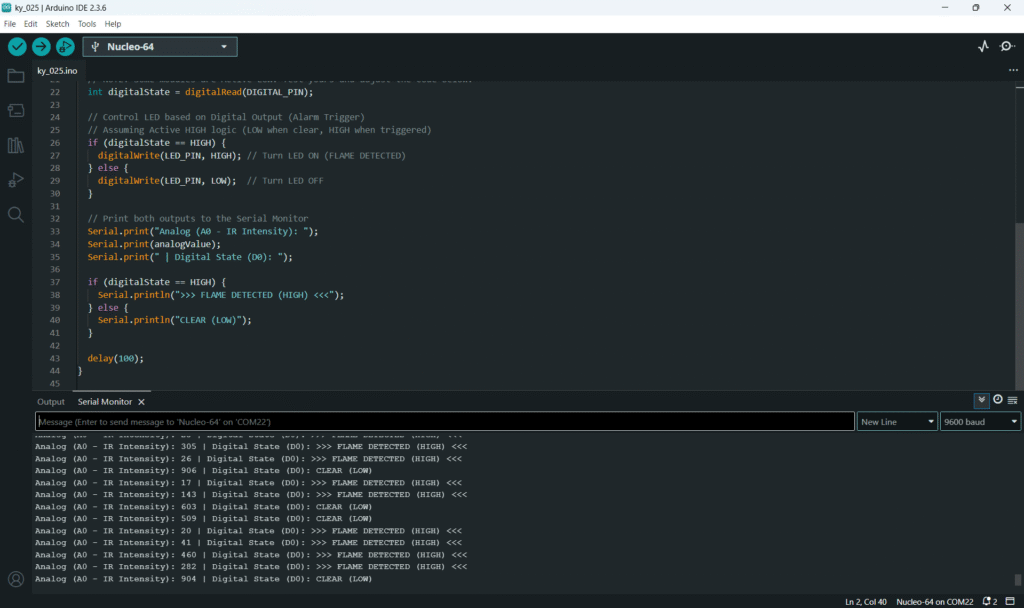
// Print both outputs to the Serial Monitor
Serial.print("Analog (A0 - IR Intensity): ");
Serial.print(analogValue);
Serial.print(" | Digital State (D0): ");
if (digitalState == HIGH) {
Serial.println(">>> FLAME DETECTED (HIGH) <<<");
} else {
Serial.println("CLEAR (LOW)");
}
delay(100);
}
Code Explanation
- Analog Reading: In a clear environment, the A0 reading will be high (e.g., 800-1000). As the IR intensity increases (closer to a flame), the reading drops (e.g., 100-300).
- D0 Output: The digital pin is controlled by the comparator. The potentiometer sets the A0 value (the IR intensity) at which the D0 pin switches state, triggering the alarm.
5. Adjusting Sensitivity (Potentiometer)
The potentiometer controls the digital switching point for the D0 pin:
- Upload the code and open the Serial Monitor.
- Note the Analog (A0) value in the current lighting conditions (your “CLEAR” baseline).
- Light your safe flame source. Hold it far away from the sensor and slowly move it closer. Watch the Analog (A0) value drop.
- Adjust the Potentiometer: Slowly turn the trimpot until the D0 pin switches state (and the Arduino LED turns ON) exactly when the flame is at your desired maximum detection distance (e.g., 30cm).
- This calibration prevents false alarms from ambient light while ensuring reliable detection of the flame.
6. Uploading and Running the Project
Step 1 – Build & Upload
Complete the standard build and upload process.
Step 2 – Test
- Calibrate the digital threshold using the potentiometer (Section 5).
- No Flame: The Arduino LED (Pin 13) should be OFF.
- Introduce Flame: Bring the small flame source closer. As it enters the calibrated range, the LED should turn ON and the Serial Monitor should show FLAME DETECTED.
7. Hands-On Lab Recap
You’ve learned:
- The principle of IR flame detection.
- How to use the analog output (A0) to monitor IR intensity.
- The crucial skill of calibrating the digital threshold for safety applications.
- How to use the D0 output for a fire alarm trigger.
This concludes the comprehensive series on fundamental KY-series modules.
8. Common Issues & Fixes
| Issue | Cause | Solution |
|---|---|---|
| Sensor is always ON (false positive). | Potentiometer is set too sensitive or ambient IR light is high. | Turn the potentiometer clockwise to decrease sensitivity. Shield the sensor from direct sunlight or bright lamps. |
| Sensor doesn't trigger even close to the flame. | Potentiometer is set too insensitive. | Turn the potentiometer counter-clockwise to increase sensitivity. Ensure your flame source is emitting IR in the 760nm to 1100nm range. |
| Analog reading is fixed at 0 or 1023. | Wiring error or VCC/GND issue. | Check the A0 pin connection to Analog Pin A0. Ensure VCC and GND are secure. |

