Arduino Tutorial: KY-028 Digital Temperature Sensor Module
Abstract
Learn how to use the KY-028 Digital Temperature Sensor Module with Arduino. This module combines an NTC thermistor with a comparator circuit, providing both a raw analog voltage (A0) related to temperature and a digital ON/OFF signal (D0) when a preset temperature threshold is crossed. This tutorial focuses on using both inputs and calibrating the digital trigger using the onboard potentiometer.
1. Introduction
The KY-028 is designed for simple, threshold-based temperature switching. It offers a dual-mode approach to temperature sensing:
- Analog Output (A0): Provides the raw voltage from the thermistor’s voltage divider circuit. This can be converted to an absolute temperature value (as demonstrated in Episode 30, KY-001), but here we use it to see the instantaneous raw value.
- Digital Output (D0): This is the main feature. An onboard comparator is wired to a potentiometer to allow you to set a specific trigger point. When the temperature crosses that point, the D0 pin instantly switches state.
In this episode, you’ll learn:
- The difference between the module’s D0 and A0 outputs.
- How to use the digital output (D0) to trigger an event (e.g., turning on a fan) when the temperature exceeds a set point.
- How to use the onboard potentiometer to set the temperature threshold without changing code.
This project enables the Arduino to perform simple, temperature-based automation.
2. Prerequisites
Make sure you have:
- An Arduino Uno or compatible board.
- One KY-028 Digital Temperature Sensor Module.
- Jumper Wires.
- Arduino IDE
- A heat source for testing (e.g., your fingers, or a warm cup of water).
3. Wiring and Setup for Arduino
The KY-028 module has four pins and requires both digital and analog input pins.
Step 1 – Identify Pins
The module typically has four pins: A0 (Analog Output), D0 (Digital Output), VCC (+), and GND (− or GND).
Step 2 – Connect the Module
Wire the module to the Arduino as follows:
- Connect the GND pin of the KY-028 to the GND pin on the Arduino.
- Connect the VCC pin of the KY-028 to the 5V pin on the Arduino.
- Connect the D0 pin of the KY-028 to Arduino Digital Pin 7 (Digital Input).
- Connect the A0 pin of the KY-028 to Arduino Analog Pin A0 (Analog Input).
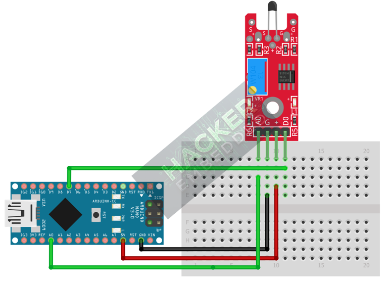
This image was created with Fritzing
Step 3 – Initialize Pin Modes
pinMode(7, INPUT); // D0 pin for digital ON/OFF detection
We will use the on-board LED (Pin 13) to reflect the digital trigger state.
4. Writing Dual-Mode Temperature Code
We will monitor both the analog reading (to see the heat level) and the digital output (to check if the temperature threshold has been crossed).
Open main.ino and implement the following code.
const int DIGITAL_PIN = 7; // D0 Output
const int ANALOG_PIN = A0; // A0 Output
const int LED_PIN = 13; // Built-in LED
void setup() {
pinMode(LED_PIN, OUTPUT);
pinMode(DIGITAL_PIN, INPUT);
Serial.begin(9600);
Serial.println("KY-028 Temp Sensor Ready! Calibrate Digital Threshold.");
}
void loop() {
// 1. Read Analog State (A0)
// Raw 0-1023 value. Higher value = Lower Resistance = HOTTER (for NTC)
int analogValue = analogRead(ANALOG_PIN);
// 2. Read Digital State (D0)
// Digital state is set by the potentiometer threshold.
// We assume LOW means the temperature threshold has been crossed (HOT).
int digitalState = digitalRead(DIGITAL_PIN);
// Control LED based on Digital Output (Action Trigger)
if (digitalState == LOW) {
digitalWrite(LED_PIN, HIGH); // Turn LED ON (Temperature Exceeded)
Serial.println(">>> DIGITAL TRIGGERED (LOW)! LED ON <<<");
} else {
digitalWrite(LED_PIN, LOW); // Turn LED OFF
}
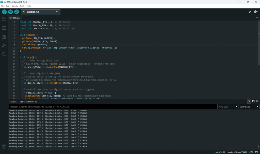
// Print both outputs to the Serial Monitor
Serial.print("Analog Reading (A0): ");
Serial.print(analogValue);
Serial.print(" | Digital State (D0): ");
if (digitalState == LOW) {
Serial.println("HOT / TRIGGERED");
} else {
Serial.println("COLD / CLEAR");
}
delay(200);
}
Code Explanation
- Analog Reading: Since the module uses an NTC thermistor (resistance decreases as temperature increases) in a voltage divider, the ADC reading will generally increase when the sensor gets hotter.
- D0 Output: The digital pin is controlled by the comparator. When the analog voltage exceeds the threshold set by the potentiometer, the D0 pin switches to LOW (Active LOW assumption for high temperature).
5. Adjusting Sensitivity (Potentiometer)
The potentiometer on the KY-028 controls the digital switching point for the D0 pin:
- Upload the code from Section 4 and open the Serial Monitor.
- Observe the current Analog Reading (A0) in the room, and note the Digital State.
- Place your finger on the sensor to warm it up. Watch the A0 value rise.
- If the digital state doesn’t switch, or switches too easily, slowly adjust the potentiometer with a small screwdriver.
- You are setting the A0 value at which the D0 pin flips state. Adjust the pot until the D0 pin switches only when your finger is warming the sensor, but remains CLEAR at room temperature.
- This sets your digital temperature threshold.
6. Uploading and Running the Project
Step 1 – Build & Upload
Complete the standard build and upload process.
Step 2 – Test
- Calibrate the digital threshold using the potentiometer (Section 5).
- Room Temperature: The Arduino LED (Pin 13) should be OFF.
- Heat the Sensor: Place your finger or another heat source on the sensor. As the A0 reading rises, the LED should turn ON and the Serial Monitor should show TRIGGERED once the calibrated threshold is crossed.
- Cool Down: Once the sensor cools back below the threshold, the LED will turn OFF.
7. Hands-On Lab Recap
You’ve learned:
- How the KY-028 provides both raw analog data and a digital threshold trigger.
- The crucial skill of calibrating the temperature set point using the onboard potentiometer.
- How to use the D0 output for temperature-based digital switching.
This concludes the comprehensive series on fundamental KY-series modules.
8. Common Issues & Fixes
| Issue | Cause | Solution |
|---|---|---|
| Digital LED is always ON or never turns ON. | Potentiometer is mis-calibrated. | Calibrate the sensor carefully (Section 5). You must set the pot so the ambient A0 reading is on one side of the threshold and the hot A0 reading is on the other. |
| Digital logic is reversed (triggers when cold). | Assumption of Active LOW for HOT is incorrect. | Change the if statement logic to if(digitalState == HIGH) to detect the trigger state. |
| Analog reading is fixed at 0 or 1023. | Wiring error or VCC/GND issue. | Check the A0 pin connection to Analog Pin A0. Ensure VCC and GND are secure. |

