
Arduino Tutorial: KY-034 Automatic Flashing Color LED
Abstract
Learn how to use the KY-034 Automatic Flashing Color LED Module with Arduino. This unique module contains a single integrated circuit (IC) that causes the LED to automatically cycle through various colors and flash patterns when simply supplied with power. This tutorial focuses on using a digital output pin to act as a software switch to control the ON/OFF state of the module.
1. Introduction
Unlike standard LEDs (like the KY-016 or KY-029) that require complex PWM code to change color, the KY-034 has its control logic built-in. When the circuit receives power, the internal IC takes over, generating the flashing, fading, and color-cycling effects automatically.
In this episode, you’ll learn:
- The principle of a self-flashing LED (integrated control logic).
- How to use a digital output pin to control the module’s power.
- How to use digitalWrite() to turn the flashing sequence ON and OFF.
- How to combine this simple output with a timing sequence to create a controlled visual alert.
This project demonstrates how a complex visual effect can be achieved with the simplest of digital controls.
2. Prerequisites
Make sure you have:
- An Arduino Uno or compatible board.
- One KY-034 Automatic Flashing Color LED Module.
- Jumper Wires.
- Arduino IDE
3. Wiring and Setup for Arduino
The KY-034 module is essentially a specialized LED and resistor/IC on a board. It only requires a power source and ground.
Step 1 – Identify Pins
The module typically has three pins: Signal (S or OUT), VCC (+), and Ground (− or GND).
Step 2 – Connect the Module
Wire the module to the Arduino as follows. Since the module is self-flashing, we use a standard digital pin to supply the 5V power (treating the pin as a switch).
- Connect the – / GND pin of the KY-034 to the GND pin on the Arduino.
- Connect the + / VCC pin of the KY-034 to the 5V pin on the Arduino.
- Connect the S / Signal pin of the KY-034 to Arduino Digital Pin 10.
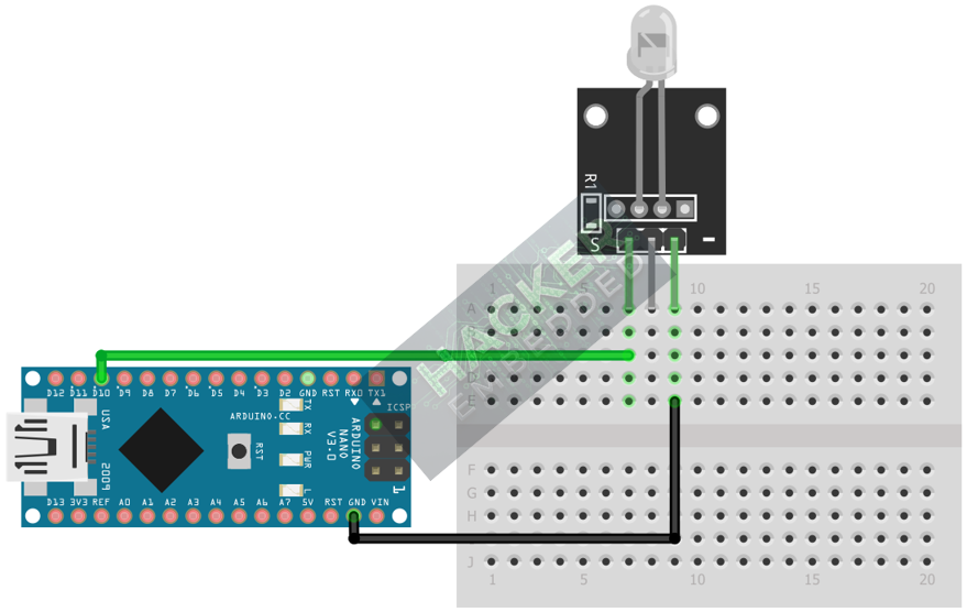
This image was created with Fritzing
Note: For the KY-034, the signal pin (S) often directly controls the LED’s power. Supplying HIGH to the S pin turns the module ON, and LOW turns it OFF.
Step 3 – Initialize Pin Mode
The signal pin must be initialized as an OUTPUT in the setup() function:
pinMode(10, OUTPUT);
4. Writing Timed Control Code
Open main.ino and implement the following code. This program uses the Arduino to control when the self-flashing LED is allowed to operate, creating a pulsed sequence of color effects.
					const int FLASH_LED_PIN = 10;

void setup() {
  pinMode(FLASH_LED_PIN, OUTPUT);
  Serial.begin(9600);
  Serial.println("KY-034 Flashing LED Test Ready!");
}

void loop() {
  // 1. Activate the Flashing Sequence (Signal HIGH)
  digitalWrite(FLASH_LED_PIN, HIGH);
  Serial.println("Flashing ON...");
  delay(1500); // Allow flashing for 1.5 seconds

  // 2. Deactivate the LED (Signal LOW)
  digitalWrite(FLASH_LED_PIN, LOW);
  Serial.println("Flashing OFF...");
  delay(1500); // Wait for 1.5 seconds
}
Code Explanation
- digitalWrite(FLASH_LED_PIN, HIGH): Sends 5V to the module’s control pin, allowing the internal IC to power up and begin its pre-programmed color cycling and flashing routine.
- digitalWrite(FLASH_LED_PIN, LOW): Cuts the control voltage, immediately shutting down the module and stopping all color and flashing effects.
- Autonomous Effect: Crucially, the color changing and flashing is handled entirely by the KY-034 module; the Arduino is only acting as a basic timer switch.
5. Creating a Short Burst Alert
This module is excellent for quick visual alerts. You can implement a function to create rapid bursts of the color effect.
					// Function to generate a short, rapid burst of the flashing color sequence
void burstFlash(int duration_ms) {
  digitalWrite(FLASH_LED_PIN, HIGH);
  delay(duration_ms);
  digitalWrite(FLASH_LED_PIN, LOW);
}

void loop() {
  // 1. Wait
  delay(3000);

  // 2. Alert: 500ms burst of flashing color
  Serial.println("Alert Burst!");
  burstFlash(500);
}
6. Uploading and Running the Project
Step 1 – Build
Click the Verify (checkmark icon) button in the Arduino IDE to compile the sketch.
Step 2 – Upload
- Connect your Arduino board via USB.
- Select the correct board and COM port.
- Click the Upload (arrow icon) button.
Step 3 – Test
- The LED on the KY-034 module should exhibit its full, complex color-changing and flashing pattern only when the digital pin is set to HIGH.
- If you run the code from Section 4, the LED should turn ON and display the effect for 1.5s, then turn completely OFF for 1.5s, repeating the cycle.
7. Hands-On Lab Recap
You’ve learned:
- How to control a component with integrated intelligence (internal IC).
- That a complex visual effect can be controlled with a simple digital HIGH/LOW switch.
- How to use the Arduino as a master timer for a sub-module’s behavior.
This module is useful for creating highly visible status indicators without consuming the Arduino’s processing power for complex PWM routines.
8. Common Issues & Fixes
| Issue | Cause | Solution |
|---|---|---|
| LED is always ON and flashing. | Wiring error: Signal pin is shorted to VCC, or logic is wrong. | Check that the S pin is correctly connected to the Arduino output pin and not accidentally touching 5V. |
| LED never turns ON. | Wiring error (GND/VCC reversed or no connection). | Double-check that 5V and GND are connected correctly and the Signal pin is set to OUTPUT. |
| LED is always a single color, not flashing. | Module is damaged or is a standard RGB LED, not a KY-034. | Verify the part number. If it is a standard LED, you must use PWM (analogWrite) for color changes. |

