Arduino Tutorial: KY-036 Metal Touch Sensor Module
Abstract
Learn how to use the KY-036 Metal Touch Sensor Module with Arduino. This module detects touch by measuring the change in electrical conductivity when a conductive material, usually a person’s finger, makes contact with its exposed pads. It provides both a digital ON/OFF signal (D0) for simple touch detection and a raw analog value (A0) representing the contact quality. This tutorial focuses on using both inputs and calibrating the digital trigger using the onboard potentiometer.
1. Introduction
The KY-036 works similarly to a basic conductivity sensor or a capacitive sensor, relying on the electrical properties of the human body (which is slightly conductive) to complete or alter a circuit:
- Analog Output (A0): Provides a continuous voltage that changes based on the quality of the conductive contact. The reading typically decreases when the touch is made.
- Digital Output (D0): An onboard comparator uses the analog signal to provide a simple, adjustable HIGH/LOW switch. The threshold for triggering the switch is set by the potentiometer, allowing you to set the required sensitivity for a touch.
In this episode, you’ll learn:
- The principle of conductive touch sensing.
- How to use the analog output (A0) to measure contact strength.
- How to use the digital output (D0) for a simple touch switch.
- How to use the onboard potentiometer to set the touch sensitivity.
This project enables the Arduino to react to human contact without mechanical switches.
2. Prerequisites
Make sure you have:
- An Arduino Uno or compatible board.
- One KY-036 Metal Touch Sensor Module.
- Jumper Wires.
- Arduino IDE
3. Wiring and Setup for Arduino
The KY-036 module has four pins and requires both digital and analog input pins.
Step 1 – Identify Pins
The module typically has four pins: A0 (Analog Output), D0 (Digital Output), VCC (+), and GND (− or GND).
Step 2 – Connect the Module
Wire the module to the Arduino as follows:
- Connect the GND pin of the KY-036 to the GND pin on the Arduino.
- Connect the VCC pin of the KY-036 to the 5V pin on the Arduino.
- Connect the D0 pin of the KY-036 to Arduino Digital Pin 7 (Digital Input).
- Connect the A0 pin of the KY-036 to Arduino Analog Pin A0 (Analog Input).
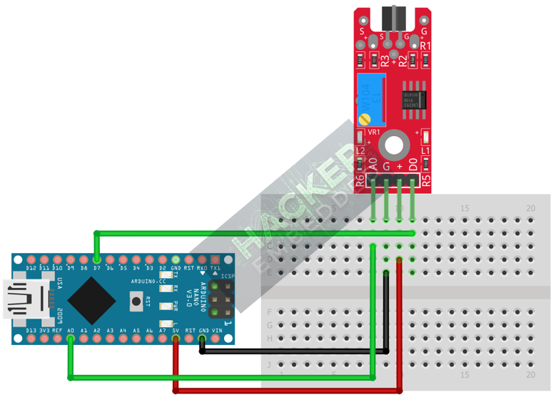
This image was created with Fritzing
Step 3 – Initialize Pin Modes
pinMode(7, INPUT); // D0 pin for digital ON/OFF detection
We will use the on-board LED (Pin 13) to reflect the digital touch state.
4. Writing Dual-Mode Touch Sensing Code
We will monitor the analog output for the contact quality and use the digital output to trigger an event based on the preset sensitivity.
Open main.ino and implement the following code.
					const int DIGITAL_PIN = 7; // D0 Output
const int ANALOG_PIN = A0; // A0 Output
const int LED_PIN = 13;    // Built-in LED

void setup() {
  pinMode(LED_PIN, OUTPUT);
  pinMode(DIGITAL_PIN, INPUT);
  Serial.begin(9600);
  Serial.println("KY-036 Touch Sensor Ready! Calibrate Digital Threshold.");
}

void loop() {
  // 1. Read Analog State (A0)
  // Raw 0-1023 value. Typically HIGH (e.g., 800-1000) when not touched.
  // Value drops LOW (e.g., 100-300) when touched.
  int analogValue = analogRead(ANALOG_PIN);

  // 2. Read Digital State (D0)
  // We assume LOW means the touch threshold has been crossed (Touched).
  int digitalState = digitalRead(DIGITAL_PIN);

  // Control LED based on Digital Output (Action Trigger)
  if (digitalState == LOW) {
    digitalWrite(LED_PIN, HIGH); // Turn LED ON (TOUCH DETECTED)
  } else {
    digitalWrite(LED_PIN, LOW);  // Turn LED OFF (No touch)
  }

  // Print both outputs to the Serial Monitor
  Serial.print("Analog Reading (A0): ");
  Serial.print(analogValue);
  Serial.print(" | Digital State (D0): ");

  if (digitalState == LOW) {
    Serial.println(">>> TOUCH DETECTED (LOW) <<<");
  } else {
    Serial.println("CLEAR (HIGH)");
  }

  delay(100);
}
Code Explanation
- Analog Reading: In the untouched state, the A0 value is typically high. When a finger makes contact, the conductivity completes or alters the circuit, causing the A0 voltage (and thus the raw ADC reading) to drop significantly.
- D0 Output: The digital pin is controlled by the comparator. The potentiometer sets the analog voltage threshold at which the D0 pin switches to LOW (Active LOW assumption for touch).
5. Adjusting Sensitivity (Potentiometer)
The potentiometer on the KY-036 controls the sensitivity of the digital switching point:
- Upload the code and open the Serial Monitor.
- Note the Analog Reading (A0) when the module is not touched (your “CLEAR” baseline).
- Touch the conductive pad with one finger and note the lowest A0 value you can achieve.
- Adjust the Potentiometer: Slowly turn the trimpot until the D0 pin switches state (and the Arduino LED turns ON) exactly when your finger makes light contact.
- Calibration: Set the pot so that ambient noise or close proximity doesn’t trigger it, but a clear touch does. If the sensitivity is too high (counter-clockwise), static electricity or nearby movement may trigger it.
6. Uploading and Running the Project
Step 1 – Build & Upload
Complete the standard build and upload process.
Step 2 – Test
- Calibrate the digital threshold using the potentiometer (Section 5).
- No Touch: The Arduino LED (Pin 13) should be OFF.
- Touch the Pad: Place your finger firmly on the exposed metal trace. The A0 reading should drop, the LED should turn ON, and the Serial Monitor should show TOUCH DETECTED.
7. Hands-On Lab Recap
You’ve learned:
- The principle of conductive touch sensing with the KY-036.
- How to use the analog output (A0) to monitor contact quality.
- The crucial skill of calibrating the digital threshold for a reliable touch input.
- How to use the D0 output for a simple, non-mechanical switch.
This concludes the comprehensive series on fundamental KY-series modules.
8. Common Issues & Fixes
| Issue | Cause | Solution |
|---|---|---|
| Digital LED is always ON or never turns ON. | Potentiometer is mis-calibrated. | Calibrate the sensor carefully (Section 5). Set the pot so the A0 value for the "TOUCH" state is on the opposite side of the threshold from the "CLEAR" state. |
| Digital triggers without actual touch. | Excessive sensitivity or static electricity. | Turn the potentiometer clockwise to decrease sensitivity. Ensure the module is not near high-frequency noise sources. |
| Analog reading is fixed at 0 or 1023. | Wiring error or VCC/GND issue. | Check the A0 pin connection to Analog Pin A0. Ensure VCC and GND are secure. |
| Touch only registers if you touch ground first. | Circuit isolation issue. | Ensure your body is not heavily grounded or isolated during testing. The sensor relies on a subtle change in conductivity. |

