STM32 HAL Tutorial: Timer-Triggered ADC Conversion for Precise Sampling
Abstract
Learn how to trigger STM32 ADC conversions using timers for precise periodic sampling. Step-by-step HAL guide for real-time embedded systems.
1. Introduction
Timer-triggered ADC conversions allow:
- Precise sampling intervals
- CPU-free periodic acquisition with DMA
- Critical for: Audio sampling, sensor fusion, and control loops
By the end of this episode, you’ll be able to:
- Configure a timer to trigger ADC
- Collect periodic samples using DMA
- Process data without missing samples
2. Prerequisites
- STM32 board with ADC and Timers
- STM32CubeIDE installed
- Knowledge of HAL, DMA, ADC and Timers
3. Timer-Triggered ADC Concept
- Timer counts → generates update event → triggers ADC conversion
- DMA moves ADC result to memory automatically
- CPU can process data asynchronously
1. Timer Configuration (The Trigger)
Block: TIMER (e.g., TIMx)
Internal Process: Count Up (The counter is running).
Action Output: Update Event (UEV)
Connection: Draw an arrow from the TIMER (Update Event) to the ADC (External Trigger Input).
Label on Arrow:
Triggers Conversion
2. ADC Operation (The Conversion)
Block: ADC (Analog-to-Digital Converter)
Internal Process 1 (Input): Analog Input Channel (Shows the physical pin receiving the analog voltage).
Internal Process 2 (Trigger): The Update Event is received, starting the conversion.
Action Output: End of Conversion (EOC) / Conversion Result
Connection 1: Draw an arrow from the ADC (Conversion Result) to the DMA Controller.
Label on Arrow:
Data Ready
Connection 2 (Optional but good for clarity): Draw a line from the ADC (EOC/EOC Interrupt) to the CPU.
Label on Arrow:
ADC Interrupt (Optional)(The DMA is doing the main work, but the ADC can still signal the CPU).
3. Data Transfer and Storage (The DMA)
Block: DMA Controller (Direct Memory Access)
Internal Process: Data Request Received from ADC.
Action: Moves the data without CPU intervention.
Block: SRAM / System Memory
Internal Process: Contains the ADC Result Buffer.
Connection: Draw an arrow from the DMA Controller to the SRAM / System Memory.
Label on Arrow:
Automatic Data Transfer
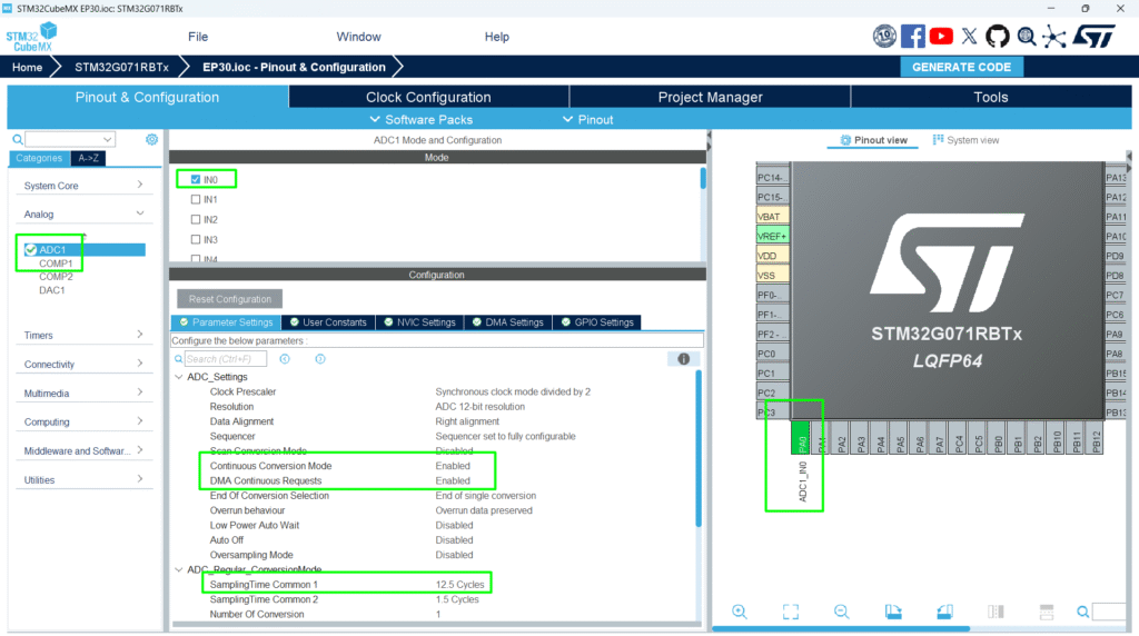
4. CubeMX Configuration
- Enable ADC
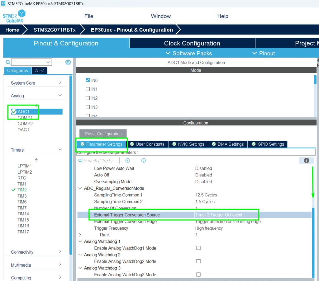
- Set External Trigger → Timer Event (e.g., TIM2 TRGO)
- Enable DMA for ADC
- Configure Timer frequency to match desired sampling rate
- Generate initialization code
5. HAL Example
// Configure ADC to be triggered by TIM2 TRGO
hadc1.Init.ExternalTrigConv = ADC_EXTERNALTRIGCONV_T2_TRGO;
HAL_ADC_Start_DMA(&hadc1, (uint32_t*)adcBuffer, BUFFER_SIZE);
// Configure Timer
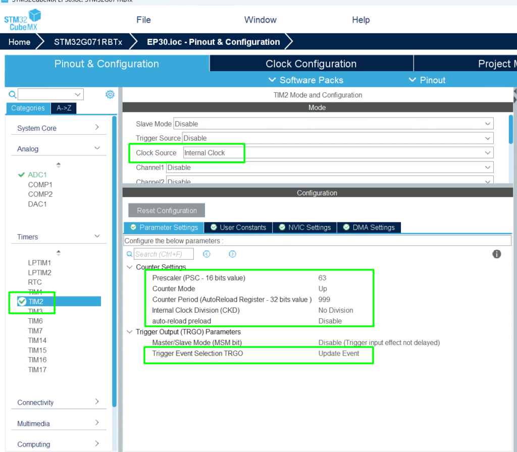
htim2.Init.Prescaler = 63;
htim2.Init.Period = 999;
HAL_TIM_Base_Init(&htim2);
HAL_TIM_Base_Start(&htim2);
- Timer frequency = system clock / (Prescaler + 1) / (Period + 1)
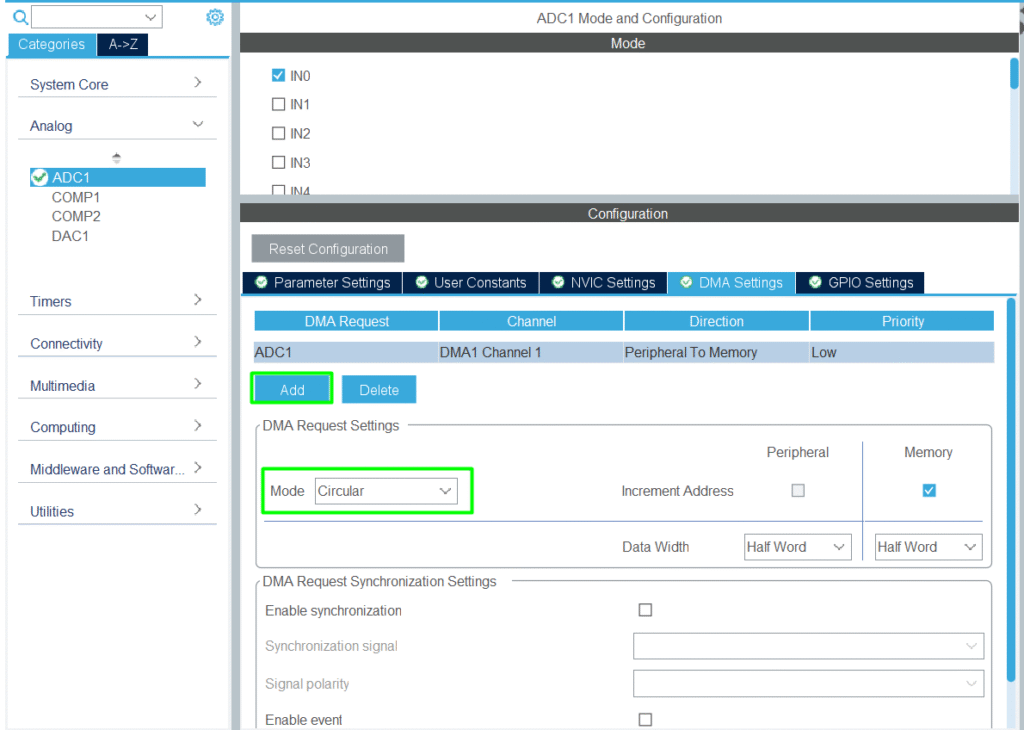
6. Hands-On Lab Example
1. Configure the analog input with DMA
2. Configure timer for 1 kHz sampling rate and enable the TRGO for the ADC
3. Go back to the ADC and enable the TIM2 as the Trigger
4. Implement the code for a constant sampling interval with no CPU intervention
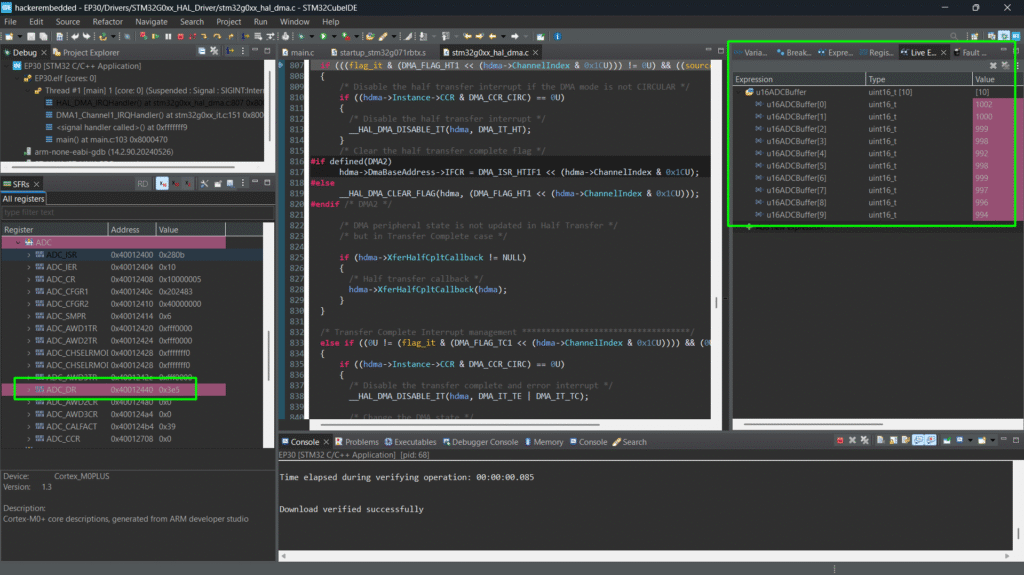
					/* USER CODE BEGIN PV */
uint16_t u16ADCBuffer[10];
/* USER CODE END PV */
					 /* USER CODE BEGIN 2 */
 HAL_ADCEx_Calibration_Start(&hadc1);
 HAL_ADC_Start_DMA(&hadc1,(uint32_t *) u16ADCBuffer, 10);
 HAL_TIM_Base_Start(&htim2);
 /* USER CODE END 2 */
5. Check the buffer during debug session using Live Watch
Tip: Combine with DAC for output generation or closed-loop control
8. Advantages
- Accurate periodic sampling without CPU overhead
- Works with DMA and circular buffers for continuous acquisition
- Essential for sensor fusion, signal processing, and closed-loop systems