STM32 HAL Tutorial: Generating Precise Pulses and PWM Signals
Abstract
Learn how to configure STM32 timers in Output Compare mode using HAL. Generate precise pulses, delays, and PWM signals with hands-on examples.
1. Introduction
Timer Output Compare (OC) allows:
- Generating precise pulses at a specific time
- Toggling GPIO pins automatically
- Triggering events or interrupts at specific counts
- Creating PWM signals for motors, LEDs, and communication
Key features:
- Compare register defines when OC event occurs
- Timer counts up (or down) until it matches the compare value
- Output state changes automatically (toggle, high, low)
2. Prerequisites
- STM32 board with TIMER
- STM32CubeIDE or VS Code installed
- Knowledge of HAL and TIMER
3. Timer Output Compare Overview
Parameter | Description |
Timer | Counts at configured frequency |
Prescaler | Reduces timer clock |
Compare value (CCR) | Timer value at which output action occurs |
Mode | Toggle, Active, Inactive, PWM |
Interrupt/OC Event | Optional to trigger callback |
Formulas:
- Pulse period: T=(CCR×(Prescaler+1))/TimerClockT = (CCR \times (Prescaler+1)) / TimerClock
- PWM duty cycle: Duty=(CCR/ARR)×100%Duty = (CCR / ARR) \times 100\%
4. Difference Between Output Compare and PWM Mode
Core Functional Differences
Output Compare Mode:
- The timer compares its counter value (TIMx_CNT) with a set value in the capture/compare register (TIMx_CCRx).
- When a match occurs, the output can be toggled, set active/inactive, or forced to a specific level, depending on the configuration.
- Used primarily for generating time-based events or toggling outputs at specific intervals.
- Example configurations include: Frozen (no effect), Toggle, Force active/inactive.
- The timer compares its counter value (TIMx_CNT) with a set value in the capture/compare register (TIMx_CCRx).
PWM (Pulse Width Modulation) Mode:
- A specialized form of output compare for generating a modulated signal with a specific frequency and duty cycle.
- The output is active or inactive based on whether the counter is less than the compare value (TIMx_CNT < TIMx_CCRx).
- Two main PWM modes:
- PWM Mode 1: Output is active as long as TIMx_CNT < TIMx_CCRx.
- PWM Mode 2: Output is inactive as long as TIMx_CNT < TIMx_CCRx.
- Commonly used for controlling motors, LEDs, and other devices requiring variable duty cycles.
- A specialized form of output compare for generating a modulated signal with a specific frequency and duty cycle.
5. CubeMX Configuration
- Select Timer (e.g., TIM3)
- Set Counter Mode = Up
- Enable Output Compare Mode on channel 1
- Select OC Mode: Toggle, Active, or PWM1/2
- Configure GPIO pin as alternate function for TIMx_CH1
- Generate HAL code
6. HAL Example: Generate a Single Pulse
					uint32_t pulseWidth = 1000; // in timer ticks

void TIM3_OC_Init(void)
{
    HAL_TIM_OC_Start_IT(&htim3, TIM_CHANNEL_1); // Start OC with interrupt
}

void HAL_TIM_OC_DelayElapsedCallback(TIM_HandleTypeDef *htim)
{
    if(htim->Channel == HAL_TIM_ACTIVE_CHANNEL_1)
    {
        // Output Compare event occurred
        // Toggle or set pin manually if needed
    }
}
- HAL_TIM_OC_Start_IT() starts OC mode with interrupt
- Callback executes when timer matches CCR value
- Useful for software-controlled events
7. HAL Example: Generate PWM Signal
					TIM_OC_InitTypeDef sConfigOC = {0};
sConfigOC.OCMode = TIM_OCMODE_PWM1;
sConfigOC.Pulse = 500; // duty cycle = CCR / ARR
sConfigOC.OCPolarity = TIM_OCPOLARITY_HIGH;

HAL_TIM_PWM_ConfigChannel(&htim3, &sConfigOC, TIM_CHANNEL_1);
HAL_TIM_PWM_Start(&htim3, TIM_CHANNEL_1);
- ARR = 1000 → duty cycle = 500/1000 = 50%
- Output pin toggles automatically, generating PWM waveform
8. Hands-On Lab Example
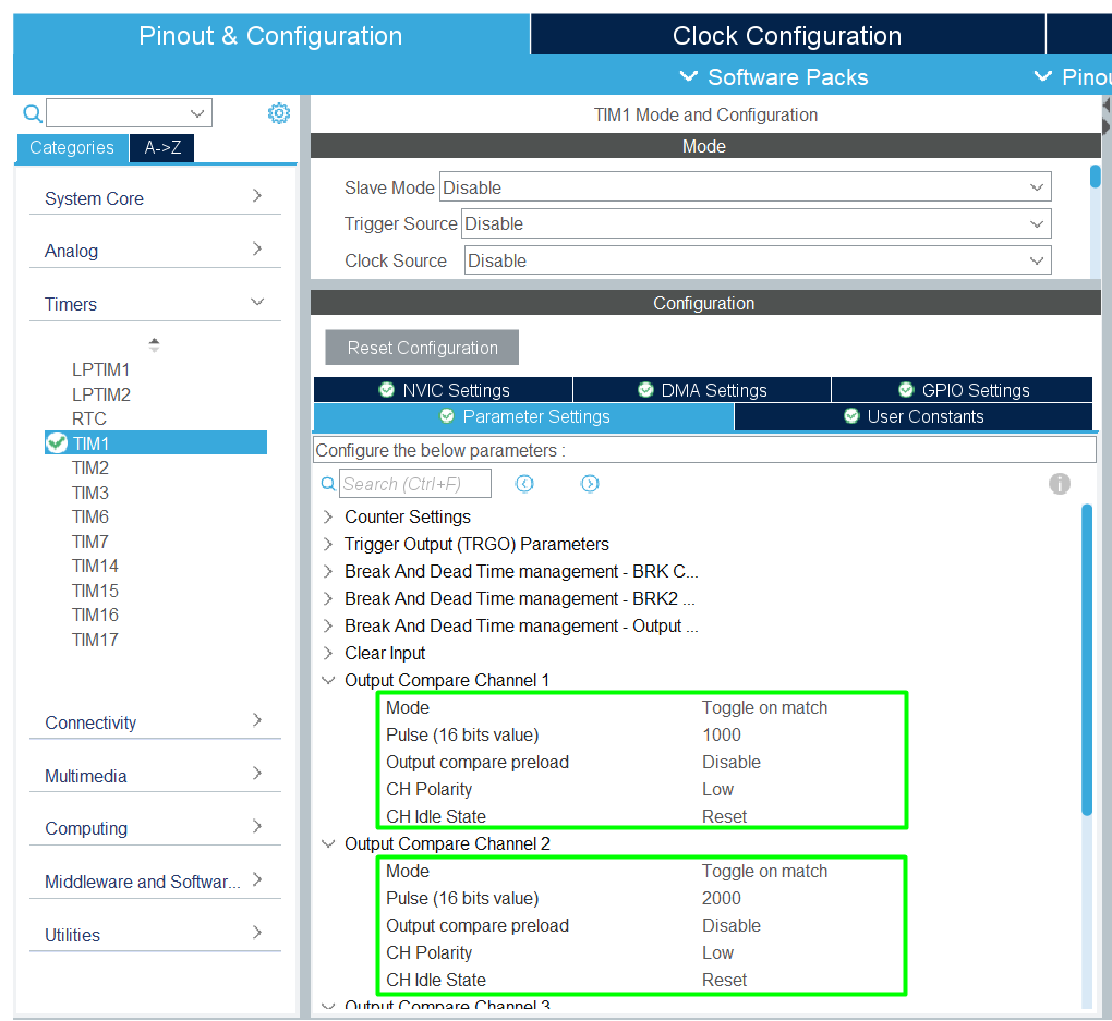
1. Configure TIM1_CH1, CH2, CH3 and CH4 in OC Toggle mode
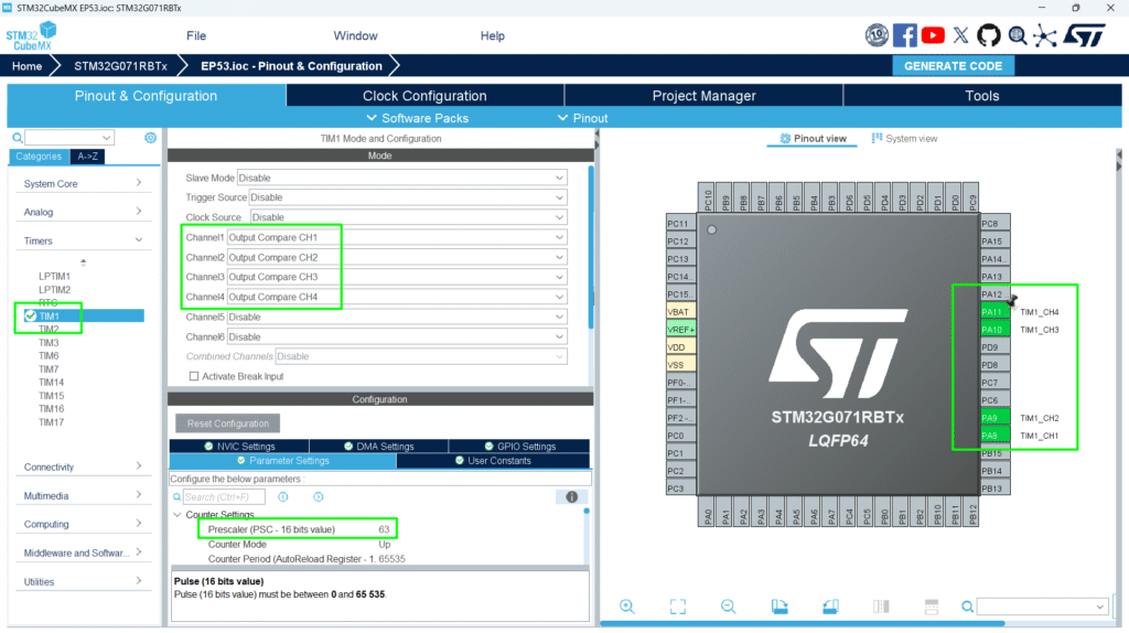
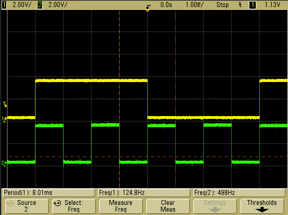
2. Set pulses for desired frequency interrupt (e.g., 1 kHz for CH1, 500 Hz for CH2, 250 Hz for CH3 and 125 Hz for CH4). Be aware that the wave form will be equivalent to a 50% duty cycle at half of the interrupt frequency.
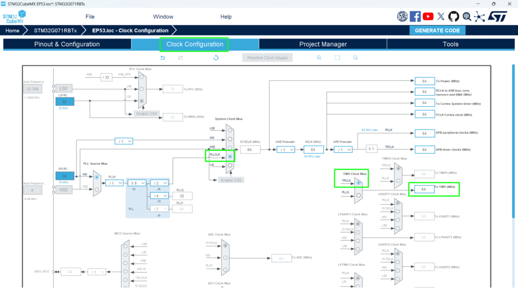
The TIM1 frequency is set to SystemCoreClock, and the objective is to get TIM1 counter clock at 1 MHz so the Prescaler is computed as following: [Prescaler = (TIM1CLK /TIM1 counter clock) – 1]. SystemCoreClock is set to 64 MHz for STM32G0xx Devices.
The TIM1 CCR1 register value is equal to 1000: [CC1 update rate = TIM1 counter clock / CCR1_Val = 1000 Hz ], so the TIM1 Channel 1 generates a periodic signal with a frequency equal to 1000 Hz.
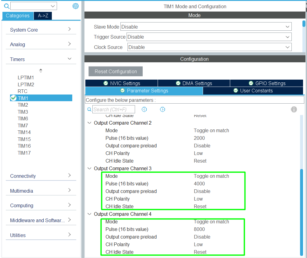
The TIM1 CCR2 register value is equal to 2000: [CC2 update rate = TIM1 counter clock / CCR2_Val = 500 Hz]. Similarly, TIM1 CCR3 will be set to 4000 [250 Hz] and CCR4 to 8000 [125 Hz].
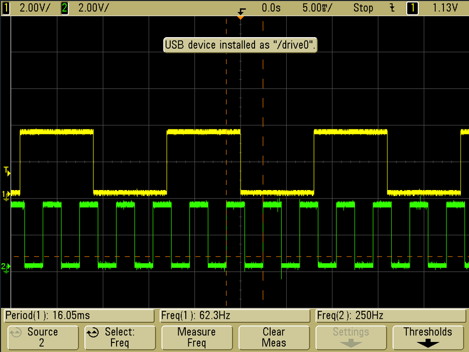
3. Connect GPIOs to oscilloscope
4. Start OCs in interrupt mode and configure the callback
					 /* USER CODE BEGIN 2 */
 HAL_TIM_OC_Start_IT(&htim1, TIM_CHANNEL_1);
 HAL_TIM_OC_Start_IT(&htim1, TIM_CHANNEL_2);
 HAL_TIM_OC_Start_IT(&htim1, TIM_CHANNEL_3);
 HAL_TIM_OC_Start_IT(&htim1, TIM_CHANNEL_4);
 /* USER CODE END 2 */
					/* USER CODE BEGIN 4 */
void HAL_TIM_OC_DelayElapsedCallback(TIM_HandleTypeDef *htim)
{
	  uint16_t autoreload_value;
	  uint32_t uhCapture = 0;
	  /* Get configured autoreload value */
	  autoreload_value = __HAL_TIM_GET_AUTORELOAD(htim);
	  /* TIM1_CH1 toggling with frequency = 1000 Hz */
	  if(htim->Channel == HAL_TIM_ACTIVE_CHANNEL_1)
	  {
	    uhCapture = HAL_TIM_ReadCapturedValue(htim, TIM_CHANNEL_1);
	    /* Set the Capture Compare Register value */
	    if (uhCapture + PULSE1 < autoreload_value)
	    {
	      __HAL_TIM_SET_COMPARE(htim, TIM_CHANNEL_1, (uhCapture + PULSE1));
	    }
	    else
	    {
	      __HAL_TIM_SET_COMPARE(htim, TIM_CHANNEL_1, (uhCapture + PULSE1) - autoreload_value);
	    }
	  }
	  /* TIM1_CH1 toggling with frequency = 500 Hz */
	  if(htim->Channel == HAL_TIM_ACTIVE_CHANNEL_2)
	  {
	    uhCapture = HAL_TIM_ReadCapturedValue(htim, TIM_CHANNEL_2);
	    /* Set the Capture Compare Register value */
	    if (uhCapture + PULSE2 < autoreload_value)
	    {
	      __HAL_TIM_SET_COMPARE(htim, TIM_CHANNEL_2, (uhCapture + PULSE2));
	    }
	    else
	    {
	      __HAL_TIM_SET_COMPARE(htim, TIM_CHANNEL_2, (uhCapture + PULSE2) - autoreload_value);
	    }
	  }
	  /* TIM1_CH1 toggling with frequency = 250 Hz */
	  if(htim->Channel == HAL_TIM_ACTIVE_CHANNEL_3)
	  {
	    uhCapture = HAL_TIM_ReadCapturedValue(htim, TIM_CHANNEL_3);
	    /* Set the Capture Compare Register value */
	    if (uhCapture + PULSE3 < autoreload_value)
	    {
	      __HAL_TIM_SET_COMPARE(htim, TIM_CHANNEL_3, (uhCapture + PULSE3));
	    }
	    else
	    {
	      __HAL_TIM_SET_COMPARE(htim, TIM_CHANNEL_3, (uhCapture + PULSE3) - autoreload_value);
	    }
	  }
	  /* TIM1_CH1 toggling with frequency = 125 Hz */
	  if(htim->Channel == HAL_TIM_ACTIVE_CHANNEL_4)
	  {
	    uhCapture = HAL_TIM_ReadCapturedValue(htim, TIM_CHANNEL_4);
	    /* Set the Capture Compare Register value */
	    if (uhCapture + PULSE4 < autoreload_value)
	    {
	      __HAL_TIM_SET_COMPARE(htim, TIM_CHANNEL_4, (uhCapture + PULSE4));
	    }
	    else
	    {
	      __HAL_TIM_SET_COMPARE(htim, TIM_CHANNEL_4, (uhCapture + PULSE4) - autoreload_value);
	    }
	  }
}
/* USER CODE END 4 */
5. Observe pin toggling at precise intervals
6. Optional: Switch to PWM mode and adjust duty cycle dynamically
Tip: Use MCO or oscilloscope to verify pulse width and frequency
9. Advantages
- Generates precise time-based pulses without CPU polling
- Can produce PWM for motors, LEDs, and analog control
- Useful for timing, delays, and signal generation
- Integrates with DMA or interrupts for advanced applications