STM32 HAL Tutorial: Analog Signal Comparison for Event Detection
Abstract
Learn how to configure and use the STM32 Comparator (COMP) peripheral with HAL. Step-by-step guide for analog signal threshold detection, event triggering, and low-power monitoring.
1. Introduction
The STM32 Comparator (COMP) allows you to compare two analog voltages and generate a digital output:
- V+ > V− → Output = HIGH
- V+ < V− → Output = LOW
Applications include:
- Overvoltage or undervoltage detection
- Zero-crossing detection for AC signals
- Threshold monitoring for sensors
- Event triggering for timers, interrupts, or DAC
By the end of this episode, you’ll be able to:
- Configure the Comparator using CubeMX and HAL
- Detect analog thresholds
Trigger interrupts or timers based on comparator output
2. Prerequisites
- STM32 board with COMP peripheral (e.g., STM32G0, STM32G4 series)
- STM32CubeIDE installed
- Basic understanding of analog signals and GPIO
3. Comparator Basics
- Inputs: Non-inverting (V+) and Inverting (V−)
- Output: Digital signal (can be routed to pin or internal peripheral)
- Polarity: Can configure output polarity (normal or inverted)
Use cases:
- Generate interrupt when sensor exceeds a threshold
- Drive PWM or DAC triggers
4. Comparator Advanced
4.1 Hysteresis:
Optional positive or negative threshold to reduce noise. A comparator compares the inverting input with the non-inverting input and even small voltage fluctuations cause bounce on the comparator output. This bounce is not acceptable in many applications. Here its possible to observe a noisy input on a comparator output shows the output bouncing when the input is noisy and the hysteresis usage:
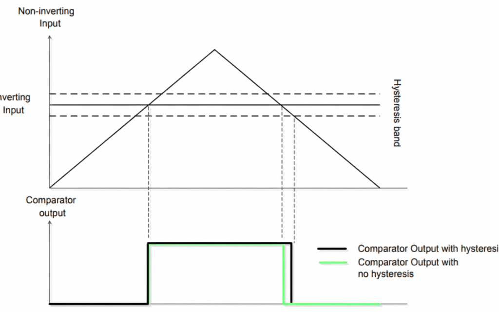
This bounce on the comparator output can be prevented by adding hysteresis into comparators. The analog comparators in some STM32 Series, such as the STM32G0 devices, have a configurable hysteresis value: no, low, medium and high hysteresis value (ranging from 0 to 30mV).
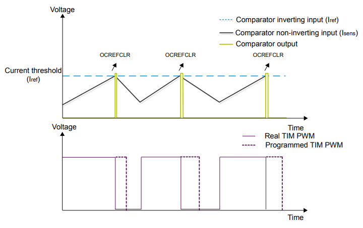
4.2 Connect the Inverting (V-) to the embedded DAC
Using the internal DAC allows the set-point has to be adjusted dynamically, fairly useful for current control, especially when associated with a timer.
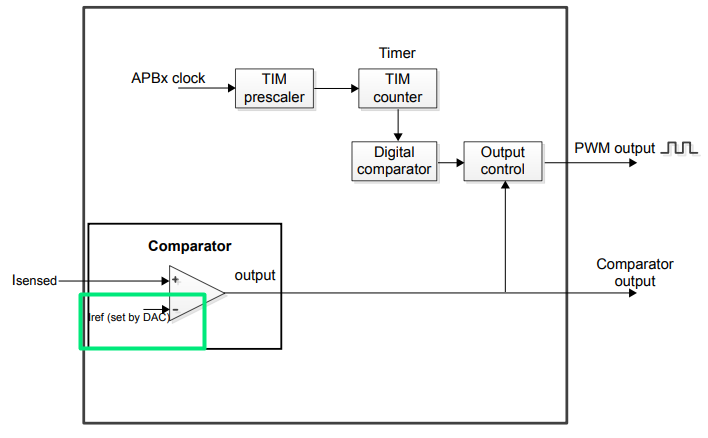
4.3 Tie the COMP with a TIMER, allowing the blanking feature
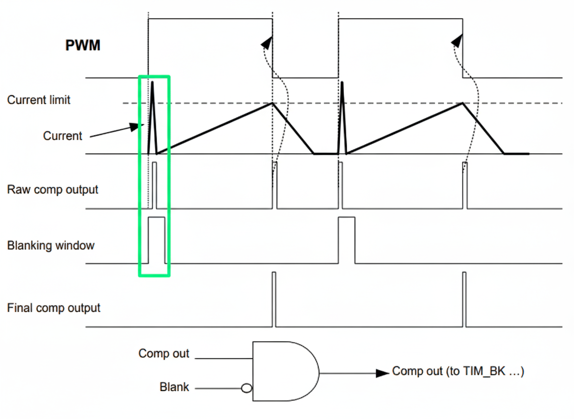
The blanking function aims to mask the output of the comparator during period of times indicated by a timer.
The comparator can be used in the cycle-by-cycle regulation loop for monitoring the peak value of the current flowing into the load. The purpose of the blanking function is to prevent incorrect current regulation tripping due to short duration current spikes at the beginning of the PWM period. Short current spikes caused by activating the power switches can produce false pulses on the comparator output – marked by the green color on the diagram:
5. CubeMX Configuration
- Enable COMP peripherals
- Select non-inverting input (V+) and inverting input (V−)Configure output polarity
- Enable interrupt via Trigger Mode
- Configure hysteresis if needed
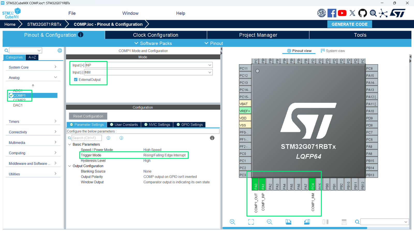
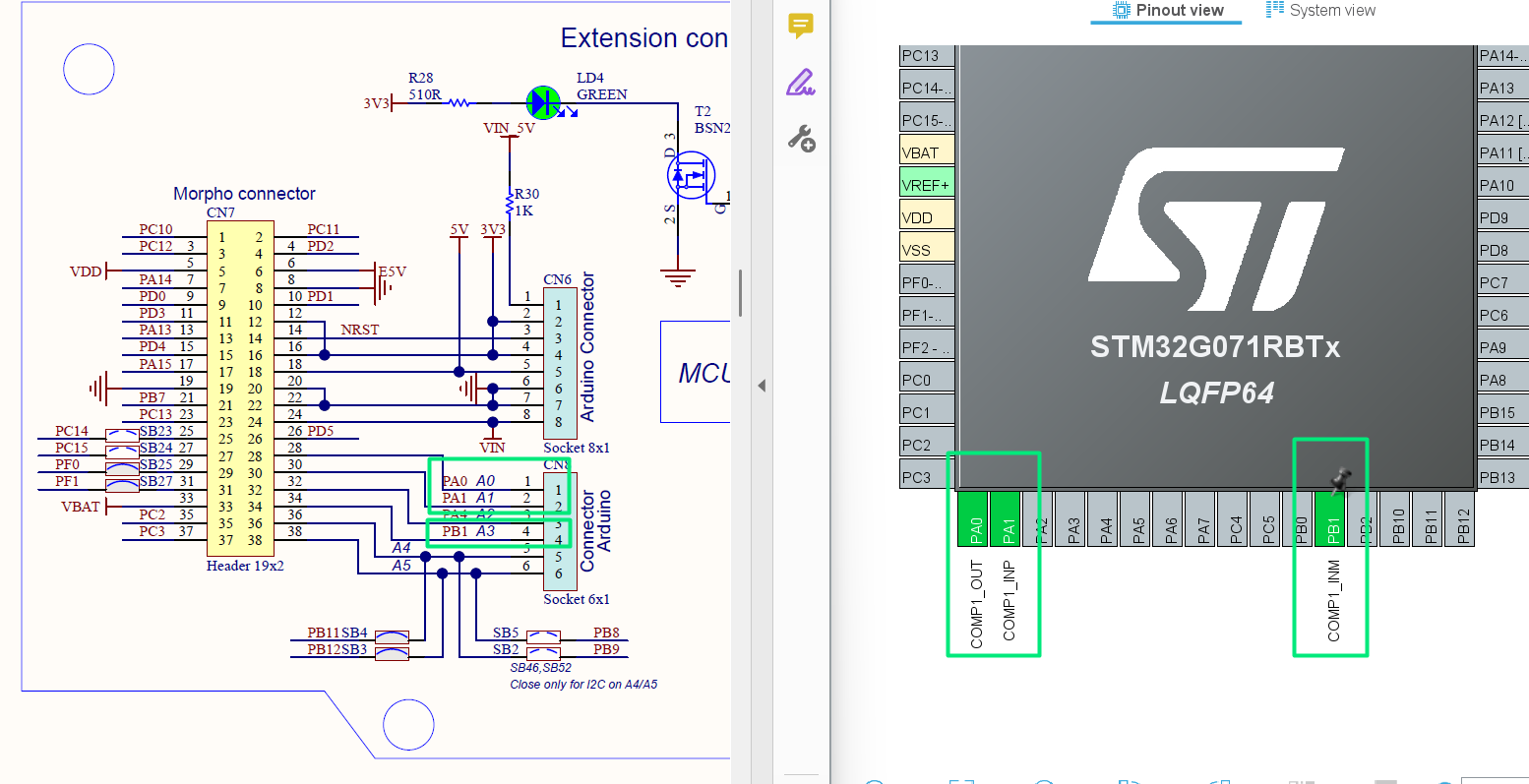
- Remap the pins to match the Arduino Connector
- Generate initialization code
6. HAL Example: Comparator Initialization
					COMP_HandleTypeDef hcomp1;

void MX_COMP1_Init(void)
{

  /* USER CODE BEGIN COMP1_Init 0 */

  /* USER CODE END COMP1_Init 0 */

  /* USER CODE BEGIN COMP1_Init 1 */

  /* USER CODE END COMP1_Init 1 */
  hcomp1.Instance = COMP1;
  hcomp1.Init.InputPlus = COMP_INPUT_PLUS_IO3;
  hcomp1.Init.InputMinus = COMP_INPUT_MINUS_IO1;
  hcomp1.Init.OutputPol = COMP_OUTPUTPOL_NONINVERTED;
  hcomp1.Init.WindowOutput = COMP_WINDOWOUTPUT_EACH_COMP;
  hcomp1.Init.Hysteresis = COMP_HYSTERESIS_HIGH;
  hcomp1.Init.BlankingSrce = COMP_BLANKINGSRC_NONE;
  hcomp1.Init.Mode = COMP_POWERMODE_HIGHSPEED;
  hcomp1.Init.WindowMode = COMP_WINDOWMODE_DISABLE;
  hcomp1.Init.TriggerMode = COMP_TRIGGERMODE_IT_RISING_FALLING;
  if (HAL_COMP_Init(&hcomp1) != HAL_OK)
  {
    Error_Handler();
  }
  /* USER CODE BEGIN COMP1_Init 2 */

  /* USER CODE END COMP1_Init 2 */

}
7. Handling Comparator Interrupts
					void HAL_COMP_TriggerCallback(COMP_HandleTypeDef *hcomp)
{
    if(hcomp->Instance == COMP1)
    {
        // Comparator output changed (V+ crossed V−)
        // Handle event (e.g., toggle LED, trigger DAC)
    }
}
- The callback is triggered on rising or falling edge depending on configuration
8. Hands-On Lab Example
- Connect variable voltage source (potentiometer) to COMP V+
- Use internal reference (Vrefint) for V−
- Configure COMP to trigger interrupt on threshold crossing
- Connect LED to MCU GPIO (PA5), as shown in this initial article: STM32: How to use GPIO and blink LED – Hacker Embedded
5. Start the COMP by calling:
					  /* USER CODE BEGIN 2 */
  HAL_COMP_Start(&hcomp1);
  /* USER CODE END 2 */
6. Observe LED toggling when input voltage crosses threshold
Tip: Combine Comparator + Timer + DAC for precision event-triggered waveform generation
9. Advantages
- Ultra-fast analog signal comparison
- Reduces CPU overhead by using interrupts
- Can trigger timers, DACs, or other peripherals
- Works in low-power modes for battery applications