STM32 Tutorial: Secure Flash and Regression Verification
Abstract
Learn how to configure STM32 Read Protection (RDP), verify its effect, and perform regression testing to ensure secure firmware operation.
1. Introduction
- RDP (Read Protection) prevents unauthorized reading or debugging of Flash memory
- Critical for secure firmware, preventing IP theft or reverse engineering
- STM32 supports multiple RDP levels:
RDP Level | Description |
Level 0 | No protection |
Level 1 | Readout protection enabled (debug and readout blocked) |
Level 2 | Permanent read protection, irreversible (chip fully locked) |
Always test RDP behavior with regression to avoid locking yourself out.
Some newer STM32 has a different RDP scheme, which allows RDP L2 regression with password and we’ll explore it in another article.
2. Prerequisites
- STM32 board with the classic RDP scheme (all STM32Fx, Lx, Gx and most of H7 series)
- STM32CubeIDE installed
- Basic understanding of option bytes
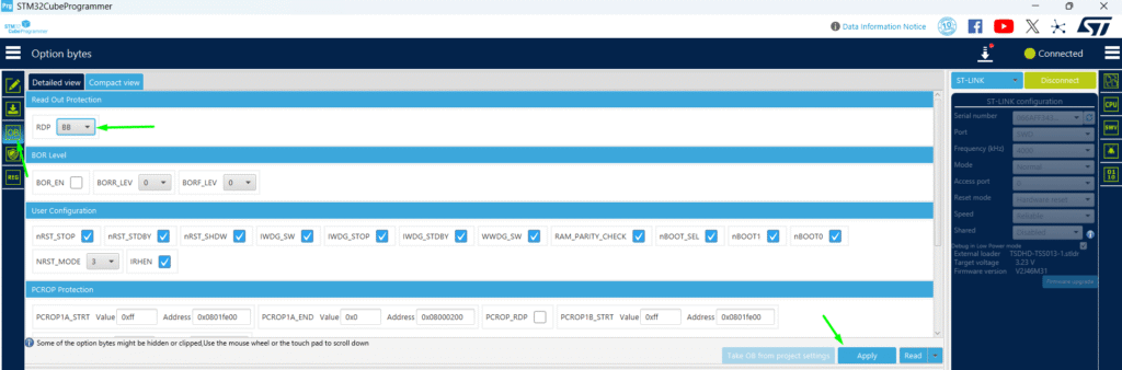
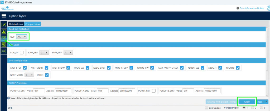
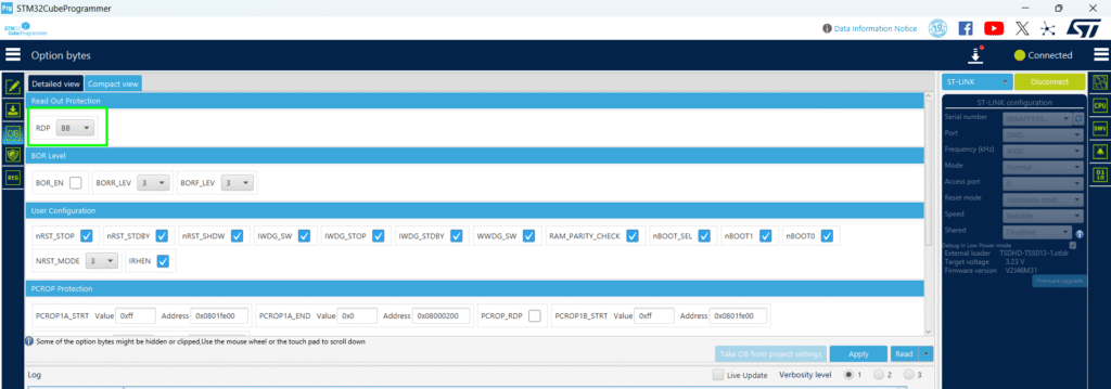
3. Setting RDP via CubeProgrammer
- Connect STM32 via SWD/JTAG or UART
- Open Option Bytes tab
- Set RDP Level 1 → click Apply
- MCU may automatically reset after programming
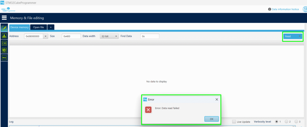
Verification:
- Attempt to read Flash or debug MCU
- Expected: access blocked or read errors
Regression via CubeProg:
- Connect STM32 via SWD/JTAG or UART
- Open Option Bytes tab
- Set RDP Level 0 and click Apply
4. Setting RDP via Firmware
The code snippet can be used to change the option byte responsible for the RDP via firmware:
					void EnableRDP(void)
{
    FLASH_OBProgramInitTypeDef OBInit;

    HAL_FLASH_Unlock();
    HAL_FLASH_OB_Unlock();

    OBInit.OptionType = OPTIONBYTE_RDP;
    OBInit.RDPLevel = OB_RDP_LEVEL1; // Level 1

    HAL_FLASHEx_OBProgram(&OBInit);
    HAL_FLASH_OB_Launch();
    //never gets here, OB_Launch resets the MCU
    HAL_FLASH_OB_Lock();
    HAL_FLASH_Lock();
}
- Unlock Flash and Option Bytes
- Program RDP and launch changes
- Lock Flash and Option Bytes
Tip: Avoid Level 2 during initial tests — it is irreversible
5. Regression Testing RDP
Goals:
- Ensure MCU blocks debug access after RDP Level 1
- Confirm application still runs correctly
- Verify option bytes retain correct configuration after reset
- Implement a function running from RAM memory to perform the RDP regression. It is important to have this code running from RAM, since by the time the firmware calls the RDP regression, it will trigger a mass erase from FLASH, invalidating the Option Byte Launch sequence, needed to update the change.
					/* USER CODE BEGIN PD */
// OPTION Byte definitions
// FACTORY default value for the OPTION BYTE is 0xDFFF E1AA.
// Target value : 0xDEFF E1AA - the nBOOT_SEL bit (bit 24) is supposed to be cleared.
#define OPTION_BYTE_TARGET_VALUE (0xDEFFE1AA)
/* USER CODE END PD */

void __attribute__((__section__(".RamFunc"))) RDP_Regression(void)
{
	__disable_irq();
	printf("Mass Erase Start\r\n");

	/* Unlock FLASH register access */
    HAL_FLASH_Unlock();

    /* Unlock option bytes operation */
	HAL_FLASH_OB_Unlock();

	/* Force readout protection level 0 */
	FLASH->OPTR = OPTION_BYTE_TARGET_VALUE;
	FLASH->CR |= FLASH_CR_OPTSTRT;
	/* Force OB Load */
	FLASH->CR |= FLASH_CR_OBL_LAUNCH;
}
6. Hands-On Lab
Program a test application → blink LED with some UART messages and the push button to change the behavior. Use the following configuration:
- PC13 configured as input, push button (BT1)
- PA5 configured as output push pull, LED (LED_GREEN)
- PA2/PA3 for UART2, configured as 115200/8/N/1
- Consider checking the printf article to get your foundation done> – Hacker Embedded How to implement printf with STM32: Setup for STM32CubeIDE and VS Code
Add the needed code. Consider using the USER CODE sections, so its easy to copy and paste on your newly created application.
					/* USER CODE END Header */
/* Includes ------------------------------------------------------------------*/
#include "main.h"

/* Private includes ----------------------------------------------------------*/
/* USER CODE BEGIN Includes */
#include "stdio.h"
/* USER CODE END Includes */

/* Private typedef -----------------------------------------------------------*/
/* USER CODE BEGIN PTD */

/* USER CODE END PTD */

/* Private define ------------------------------------------------------------*/
/* USER CODE BEGIN PD */
// OPTION Byte definitions
// FACTORY default value for the OPTION BYTE is 0xDFFF E1AA.
// Target value : 0xDEFF E1AA - the nBOOT_SEL bit (bit 24) is supposed to be cleared.
#define OPTION_BYTE_TARGET_VALUE (0xDEFFE1AA)
/* USER CODE END PD */

/* Private macro -------------------------------------------------------------*/
/* USER CODE BEGIN PM */

/* USER CODE END PM */

/* Private variables ---------------------------------------------------------*/
UART_HandleTypeDef huart2;

/* USER CODE BEGIN PV */

/* USER CODE END PV */

/* Private function prototypes -----------------------------------------------*/
void SystemClock_Config(void);
static void MX_GPIO_Init(void);
static void MX_USART2_UART_Init(void);
/* USER CODE BEGIN PFP */

/* USER CODE END PFP */

/* Private user code ---------------------------------------------------------*/
/* USER CODE BEGIN 0 */
int __io_putchar(int ch)
{
	HAL_UART_Transmit(&huart2, (uint8_t *)&ch, 1, 100);
	return ch;
}

void __attribute__((__section__(".RamFunc"))) RDP_Regression(void)
{
	__disable_irq();
	printf("Mass Erase Start\r\n");

	/* Unlock FLASH register access */
    HAL_FLASH_Unlock();

    /* Unlock option bytes operation */
	HAL_FLASH_OB_Unlock();

	/* Force readout protection level 0 */
	FLASH->OPTR = OPTION_BYTE_TARGET_VALUE;
	FLASH->CR |= FLASH_CR_OPTSTRT;
	/* Force OB Load */
	FLASH->CR |= FLASH_CR_OBL_LAUNCH;
}

void ToggleLED(void)
{
	if(HAL_GPIO_ReadPin(LED_GREEN_GPIO_Port, LED_GREEN_Pin))
	{
		printf("\033[5;32mLED\033[0m \r\n");
		HAL_GPIO_WritePin(LED_GREEN_GPIO_Port, LED_GREEN_Pin, GPIO_PIN_RESET);
	}
	else
	{
		printf("\033[1;32mLED\033[0m \r\n");
		HAL_GPIO_WritePin(LED_GREEN_GPIO_Port, LED_GREEN_Pin, GPIO_PIN_SET);
	}
	HAL_Delay(2000);
}

/* USER CODE END 0 */

/**
 * @brief  The application entry point.
 * @retval int
 */
int main(void)
{

	/* USER CODE BEGIN 1 */
	FLASH_OBProgramInitTypeDef OptionsBytesStruct;
	/* USER CODE END 1 */


	/* MCU Configuration--------------------------------------------------------*/

	/* Reset of all peripherals, Initializes the Flash interface and the Systick. */
	HAL_Init();

	/* USER CODE BEGIN Init */

	/* USER CODE END Init */

	/* Configure the system clock */
	SystemClock_Config();

	/* USER CODE BEGIN SysInit */
	HAL_FLASHEx_EnableDebugger();
	/* USER CODE END SysInit */

	/* Initialize all configured peripherals */
	MX_GPIO_Init();
	MX_USART2_UART_Init();
	/* USER CODE BEGIN 2 */
	printf("\033[0m");
	if (__HAL_RCC_GET_FLAG(RCC_FLAG_OBLRST))
	{
		printf("OBL flag\r\n");
	}
	__HAL_RCC_CLEAR_RESET_FLAGS();
	printf("clear all RCC flags\r\n");

	HAL_FLASHEx_OBGetConfig(&OptionsBytesStruct);
	if(OptionsBytesStruct.RDPLevel == OB_RDP_LEVEL_1)
	{
		printf("RDP LVL1 \r\n");
		printf("wait BT1 to be pressed\r\n");
		while(HAL_GPIO_ReadPin(BT1_GPIO_Port, BT1_Pin) == GPIO_PIN_SET)
		{
			;
		}
		printf("wait BT1 to be released\r\n");
		while(HAL_GPIO_ReadPin(BT1_GPIO_Port, BT1_Pin) == GPIO_PIN_RESET)
		{
			;
		}
		while(HAL_FLASH_Unlock() != HAL_OK)
		{
			printf("Waiting Flash Unlock\r\n");
		}
		while(HAL_FLASH_OB_Unlock() != HAL_OK)
		{
			printf("Waiting OB Unlock\r\n");
		}
		printf("RDP regression LV0 init\r\n");
		RDP_Regression();
	}
	/* USER CODE END 2 */

	/* Infinite loop */
	/* USER CODE BEGIN WHILE */
	while (1)
	{
		/* USER CODE END WHILE */

		/* USER CODE BEGIN 3 */
		printf("\033[96mPress BT1 to change Option Bytes\033[0m \r\n");
		if(HAL_GPIO_ReadPin(BT1_GPIO_Port, BT1_Pin) == GPIO_PIN_RESET)
		{
			printf("BT1 pressed\r\n");
			while(HAL_FLASH_Unlock() != HAL_OK)
			{
				printf("Waiting Flash Unlock\r\n");
			}
			while(HAL_FLASH_OB_Unlock() != HAL_OK)
			{
				printf("Waiting OB Unlock\r\n");
			}
			OptionsBytesStruct.OptionType = OPTIONBYTE_USER | OPTIONBYTE_RDP ; //Configure RDP
			OptionsBytesStruct.RDPLevel = OB_RDP_LEVEL_1;
			while(HAL_FLASHEx_OBProgram(&OptionsBytesStruct) != HAL_OK)
			{
				printf("Waiting OB Program\r\n");
			}
			printf("OB RDP 1 is set\r\n");
			SET_BIT(FLASH->CR, FLASH_CR_OPTSTRT);
			SET_BIT(FLASH->CR, FLASH_CR_OPTSTRT);
			while((FLASH->SR & FLASH_SR_BSY1) != 0);
			printf("OBLauch\r\n");
			while(HAL_FLASH_OB_Launch()!= HAL_OK)
			{
				printf("OBLauch Failed..retry with IWDG and StandBy Mode\r\n");
			}
		}
		else
		{
			ToggleLED();
		}
	}
	/* USER CODE END 3 */
}
Once the code is loaded, don’t attempt using the debug interface, as RDP will be set to L1. Instead, monitor the application via the Tera Term:
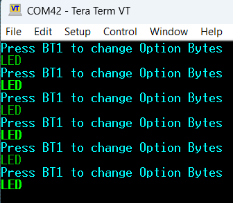
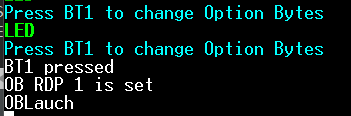
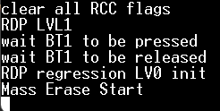
Press and hold the BT1 until the following message is displayed, indicating the RDP is now changed to L1:
Once RDP is set, it’s possible to check the configuration value via CubeProg:
You might need to power cycle after the CubeProg connection test. Once a power cycle takes place, you might also need to reset to ensure you see the message on the terminal, but it should display like this, including the press and release of button to ensure the regression takes place:
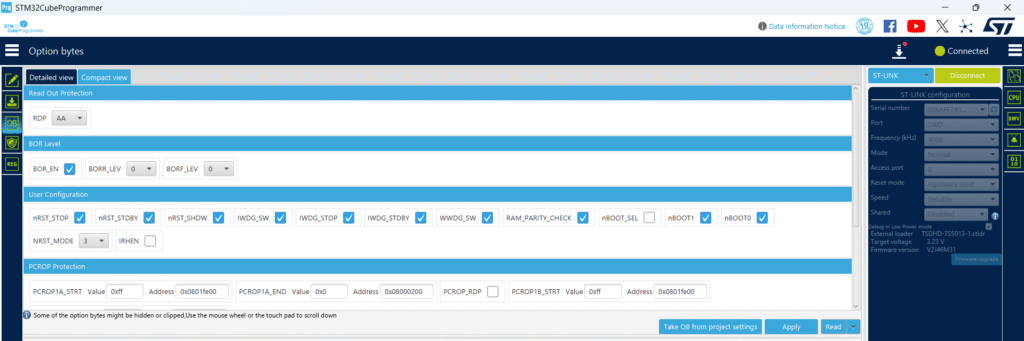
After that, you can reconnect via CubeProg to ensure the memory was indeed mass erased and RDP is back to L0:
7. Advantages of Regression Testing
- Confirms RDP prevents unauthorized Flash access
- Validates firmware behavior is not affected by protection
- Ensures option bytes retain configuration after resets or power cycles
- Reduces risk of accidental MCU lockout