How to play audio with STM32
Learn how to implement audio on the STM32N6-DK board. This guide covers SAI configuration, WM8904 codec setup, and playing 16-bit PCM mono audio via DMA.
Abstract
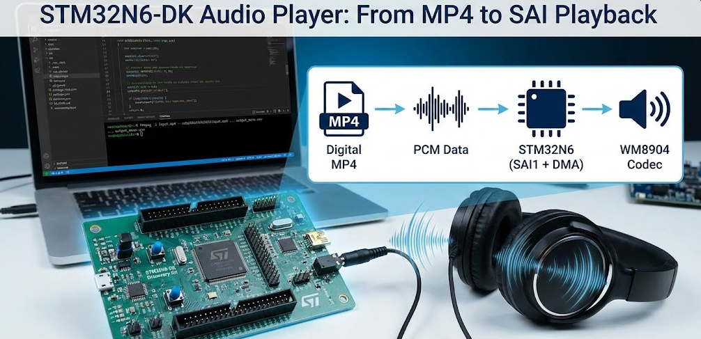
This article shows how to build a simple audio player on the STM32N6-DK board using the on-board WM8904 codec and the SAI1 peripheral. Starting from an MP4 file on a PC, we convert the audio to a WAV/PCM format suitable for STM32, briefly explain the WAV structure, and then focus on a minimal, practical demo: a pre‑generated mono PCM buffer (audio_samples_16k[]) is compiled into the firmware and played out through SAI using DMA in fixed‑size chunks. For simplicity, the demo just plays the entire content via DMA, without any runtime WAV header parsing or file system access.
1. Introduction
The STM32N6-DK Discovery Kit is a powerful evaluation platform featuring the STM32N6 microcontroller and a WM8904 audio codec. The board is suitable for:
Voice prompts and system tones
GUI/HMI demonstrations with audio feedback
Proof-of-concept multimedia/AI integration
While the WM8904 codec supports stereo audio, this article intentionally uses mono 16‑bit PCM at 16 kHz to keep things simple and reduce memory/DMA load.
The main objectives of this article are:
Show how to convert an MP4 audio track into a WAV with the correct format.
Explain the basics of the WAV header and PCM data layout.
Configure SAI1 on STM32N6-DK for 16‑bit, mono, 16 kHz playback.
Demonstrate DMA-based audio playback using a pre‑generated PCM buffer stored in flash.
The final result is a compact, easy-to-understand audio playback demo that can be used as a starting point for more advanced applications (e.g., streaming from SD card, file selection, stereo, etc.).
2. Prerequisites
To follow this tutorial, you will need:
- FFmpeg installed> FFmpeg. Optionally, have the FFmpeg added to your system’s PATH. This facilitates the usage, but its not mandatory
- Source Material: Video material in MP4 files (1080p or 720p). We collected the video from Google’s Gemini Veo 3.1
- Evaluation Board: STM32N6570-DK | Product – STMicroelectronics
- Storage: On board NOR FLASH memory controlled via HSPI interface connected to your STM32 to handle the increased file sizes of MJPEG and WAV.
- ST software: STM32CubeMX, STM32CubeIDE, STM32CubeProg and TouchGFX
Headphones or powered speakers connected to the STM32N6-DK audio output (check the board user manual for the correct jack and jumpers).
- Entire project and source code> https://github.com/hackerembedded/STM32_Workspace/tree/main/SAI_Audio
Prerequisites: Project Setup Summary
At a high level, the project will:
Initialize clocks and peripherals (SAI, DMA, I2C for WM8904, GPIO, etc.).
Configure the WM8904 codec via BSP/I2C.
Include a generated C file (audio_samples_16k.c) with the PCM data.
Start DMA playback from this buffer through SAI1.
The following sections provide the details.
3. Base Implementation to play audio with STM32
On the PC side, we start from a typical audio/video file (e.g., input.mp4) and convert it to a 16 kHz mono WAV with 16‑bit little‑endian PCM samples using ffmpeg.
Run this command in a terminal (cmd, PowerShell, bash):
ffmpeg -i "input.mp4" -vn -ar 16000 -ac 1 -c:a pcm_s16le "output_mono.wav"
Explanation of the options:
-vn
Discards the video stream, keeping only audio.-ar 16000
Sets the sample rate to 16 kHz.16 kHz is a good compromise between quality and memory/bandwidth for voice prompts or simple sounds.
STM32 can also easily handle higher sample rates (e.g., 48 kHz) if needed.
-ac 1
Produces mono audio.This halves the data throughput compared to stereo and simplifies SAI usage (mono mode) as well as memory requirements.
-c:a pcm_s16le
Outputs signed 16‑bit, little‑endian PCM samples.This matches the STM32N6 and Cortex‑M endianness.
Samples can be sent directly to SAI without byte‑swapping.
3.1 Audio Conversion (wav to C)
The resulting output_mono.wav file is then used as input to a small conversion utility or script (on PC) that:
Reads the file.
Skips the 44‑byte WAV header.
Extracts the raw 16‑bit mono PCM samples.
Generates a C source file, for example audio_samples_16k.c, containing:
					#include <stdint.h>

const int16_t audio_samples_16k[] = {
    20041, 20294, 21321, 21574, 13, 0, 24908, 26230, 12854, 14382, 12590, 12848,
    0, 24932, 24948, -6144, 3, 0, 0, 0, 0, 0, 0, 0,
    /* ... many more samples ... */
};
This PCM array is what the STM32 will play — no header at runtime, only raw samples.
This is the simple python script that can accomplish that:
					import struct

input_wav = "output_mono1.wav"
output_c = "audio_data1.c"

def wav_to_c_array(infile, outfile):
    with open(infile, "rb") as f:
        # Skip the 44-byte WAV header to get raw PCM data
        f.seek(44)
        data = f.read()

    # Convert binary bytes to 16-bit signed integers (Little Endian)
    samples = struct.unpack(f'<{len(data)//2}h', data)

    with open(outfile, "w") as f:
        f.write('#include <stdint.h>\n\n')
        # Use 'const' to ensure the data stays in Flash and doesn't consume RAM
        f.write('const int16_t audio_samples_16k[] = {\n    ')

        for i, sample in enumerate(samples):
            f.write(f"{sample}, ")
            if (i + 1) % 12 == 0:  # New line every 12 samples for readability
                f.write("\n    ")

        f.write('\n};\n\n')
        f.write(f'const uint32_t audio_samples_count = {len(samples)};\n')

wav_to_c_array(input_wav, output_c)
print(f"Generated {output_c}")
3.2 Basics of Audio Files and WAV Format
Even though the demo does not parse a WAV file at runtime, it is important to understand the format we generate with ffmpeg, because:
It explains why we choose pcm_s16le, mono, 16 kHz.
It allows you to later extend the demo to read WAV files from SD card, USB, etc.
WAV as container + PCM data
A simple PCM WAV file is composed of:
A 44‑byte header with metadata:
File type (“RIFF”, “WAVE”)
Audio format (PCM)
Sample rate
Number of channels
Bits per sample
Size of the data chunk
The data chunk: raw PCM samples, tightly packed.
A typical PCM WAV header can be represented in C as:
					#include <stdint.h>
#include <string.h>

typedef struct __attribute__((packed)) {
    // RIFF Chunk Descriptor
    uint8_t  ChunkID[4];        // "RIFF"
    uint32_t ChunkSize;         // Size of the entire file - 8 bytes
    uint8_t  Format[4];         // "WAVE"

    // "fmt " sub-chunk
    uint8_t  Subchunk1ID[4];    // "fmt "
    uint32_t Subchunk1Size;     // 16 for PCM
    uint16_t AudioFormat;       // 1 for PCM
    uint16_t NumChannels;       // 1 for Mono, 2 for Stereo
    uint32_t SampleRate;        // e.g., 16000 or 44100
    uint32_t ByteRate;          // SampleRate * NumChannels * BitsPerSample/8
    uint16_t BlockAlign;        // NumChannels * BitsPerSample/8
    uint16_t BitsPerSample;     // 8, 16, etc.

    // "data" sub-chunk
    uint8_t  Subchunk2ID[4];    // "data"
    uint32_t Subchunk2Size;     // NumSamples * NumChannels * BitsPerSample/8
} WAV_Header_t;
In a file‑based design running on STM32, you would:
Read the first 44 bytes into a WAV_Header_t.
Check ChunkID == “RIFF”, Format == “WAVE”, NumChannels, SampleRate, BitsPerSample, etc.
Then start streaming from buffer + sizeof(WAV_Header_t).
Validation example (reference)
For completeness, here is a pseudo-code reference validation function:
					int ValidateWavHeader(WAV_Header_t *header) {
    // Check for "RIFF" and "WAVE" signatures
    if (strncmp((char*)header->ChunkID, "RIFF", 4) != 0 ||
        strncmp((char*)header->Format, "WAVE", 4) != 0) {
        return -1; // Not a valid WAV file
    }

    // Example constraints: 16 kHz, mono, 16-bit
    if (header->SampleRate != 16000) return -2;    // Wrong frequency
    if (header->NumChannels != 1)    return -3;    // Not Mono
    if (header->BitsPerSample != 16) return -4;    // Not 16-bit

    return 0; // Header is valid and compatible
}
You can adjust the constraints according to your SAI configuration.
In this article, we’ll rely on the script that already provides the audio in array format. This allows the firmware to stay minimal and focus entirely on audio playback via DMA.
4. Theory on how Play Audio with STM32
The STM32N6-DK uses SAI1 connected to the WM8904 codec. For this demo we configure:
16‑bit data
Mono mode
Master transmit at 16 kHz
Below is the SAI configuration function (CubeMX generated, there are no minor adaptations):
					static void MX_SAI1_Init(void)
{

  /* USER CODE BEGIN SAI1_Init 0 */

  /* USER CODE END SAI1_Init 0 */

  /* USER CODE BEGIN SAI1_Init 1 */

  /* USER CODE END SAI1_Init 1 */
  hsai_BlockA1.Instance = SAI1_Block_A;
  hsai_BlockA1.Init.Protocol = SAI_FREE_PROTOCOL;
  hsai_BlockA1.Init.AudioMode = SAI_MODEMASTER_TX;
  hsai_BlockA1.Init.DataSize = SAI_DATASIZE_16;
  hsai_BlockA1.Init.FirstBit = SAI_FIRSTBIT_MSB;
  hsai_BlockA1.Init.ClockStrobing = SAI_CLOCKSTROBING_FALLINGEDGE;
  hsai_BlockA1.Init.Synchro = SAI_ASYNCHRONOUS;
  hsai_BlockA1.Init.OutputDrive = SAI_OUTPUTDRIVE_ENABLE;
  hsai_BlockA1.Init.NoDivider = SAI_MASTERDIVIDER_ENABLE;
  hsai_BlockA1.Init.FIFOThreshold = SAI_FIFOTHRESHOLD_1QF;
  hsai_BlockA1.Init.AudioFrequency = SAI_AUDIO_FREQUENCY_16K;
  hsai_BlockA1.Init.SynchroExt = SAI_SYNCEXT_DISABLE;
  hsai_BlockA1.Init.MckOutput = SAI_MCK_OUTPUT_ENABLE;
  hsai_BlockA1.Init.MonoStereoMode = SAI_MONOMODE;
  hsai_BlockA1.Init.CompandingMode = SAI_NOCOMPANDING;
  hsai_BlockA1.Init.TriState = SAI_OUTPUT_NOTRELEASED;
  hsai_BlockA1.Init.PdmInit.Activation = DISABLE;
  hsai_BlockA1.Init.PdmInit.MicPairsNbr = 1;
  hsai_BlockA1.Init.PdmInit.ClockEnable = SAI_PDM_CLOCK1_ENABLE;
  hsai_BlockA1.FrameInit.FrameLength = 32;
  hsai_BlockA1.FrameInit.ActiveFrameLength = 16;
  hsai_BlockA1.FrameInit.FSDefinition = SAI_FS_CHANNEL_IDENTIFICATION;
  hsai_BlockA1.FrameInit.FSPolarity = SAI_FS_ACTIVE_LOW;
  hsai_BlockA1.FrameInit.FSOffset = SAI_FS_BEFOREFIRSTBIT;
  hsai_BlockA1.SlotInit.FirstBitOffset = 0;
  hsai_BlockA1.SlotInit.SlotSize = SAI_SLOTSIZE_16B;
  hsai_BlockA1.SlotInit.SlotNumber = 2;
  hsai_BlockA1.SlotInit.SlotActive = 0x00000003;
  if (HAL_SAI_Init(&hsai_BlockA1) != HAL_OK)
  {
    Error_Handler();
  }
  /* USER CODE BEGIN SAI1_Init 2 */

  /* USER CODE END SAI1_Init 2 */

}
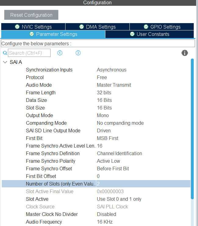
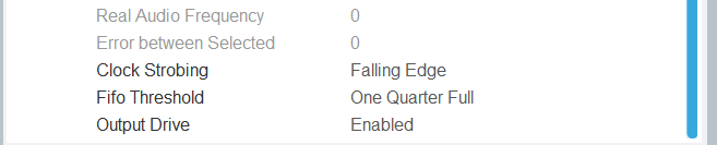
Key points:
AudioFrequency = SAI_AUDIO_FREQUENCY_16K matches our 16 kHz PCM data.
DataSize = SAI_DATASIZE_16 matches our 16‑bit samples (int16_t).
MonoStereoMode = SAI_MONOMODE simplifies usage for a mono source.
The frame is configured with length 32 bits (two 16‑bit slots) and both slots active; the codec will receive data in an I2S‑compatible frame.
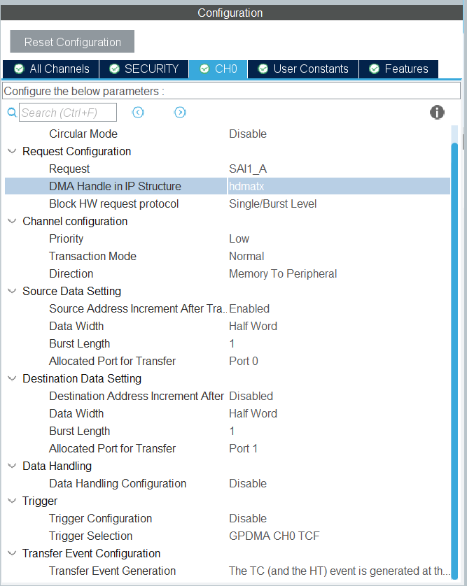
In addition to SAI, you must:
Configure DMA for SAI Tx in CubeMX (Memory-to-Peripheral, normal mode is enough for this demo).
Initialize the WM8904 codec via BSP/I2C (e.g., BSP_AUDIO_OUT_Init(…)), setting it to 16 kHz, 16 bits, compatible with SAI.
PCM buffer in flash
We compile the pre‑generated PCM buffer into the application:
					#include <stdint.h>

const int16_t audio_samples_16k[] = {
    20041, 20294, 21321, 21574, 13, 0, 24908, 26230, 12854, 14382, 12590, 12848,
    0, 24932, 24948, -6144, 3, 0, 0, 0, 0, 0, 0, 0,
    /* ... continues until completion ... */
};

const uint32_t audio_samples_count = XYZ; //the real number is created by the python script automatically
You may optionally place this array in a specific memory section (e.g., external flash) using, which will do on Part 3, and adjust your linker script accordingly. For this initial simple demo, the selected audio file is small enough to fit whin the FSBL space (511 KB total, between RAM and emulated FLASH).
					const int16_t audio_samples_16k[] __attribute__((section(".extflash"))) = {
    /* ... */
};
Playback strategy
For simplicity, the demo:
Does not use circular buffers but implements a semi-continuous streaming. Only stopping at the end of each chunk to update the next portion.
Does not parse any header at runtime.
Simply plays the entire content via DMA in fixed-size chunks to stay within DMA transfer size limits.
The idea:
Divide the full buffer into equal chunks. Again, for simplicity, no strict management was implemented, given the audio file size selected, its possible to divide it by 16 with just 1 byte being left out, which will be ignored. In real applications, the buffer size should be evaluated, divided by a factor that doesn’t go beyond the DMA length capability and that manages the remaining bytes and adjust the last transfer size.
Start a DMA transfer for chunk i.
When the transfer completes, the DMA callback sets a flag.
The main loop then starts DMA for the next chunk.
Once chunk 15 is played, the index is reset to 0 (loop playback) or you can stop if you prefer one-shot playback.
					//variables
volatile uint8_t PcmBufferCplt   = 0;
volatile uint8_t PlaybackStarted = 0;
uint32_t i = 0;  // chunk index
//Main loop snippet:

while (1)
{
    if (PlaybackStarted == 0)
    {
        if (HAL_OK != HAL_SAI_Transmit_DMA(
                &hsai_BlockA1,
                (uint8_t *)&audio_samples_16k[0 + (i * audio_samples_count / 16)],
                audio_samples_count / 16))
        {
            Error_Handler();
        }
        PlaybackStarted = 1;
    }

    if (PcmBufferCplt == 1)
    {
        PcmBufferCplt  = 0;
        PlaybackStarted = 0;
        i++;
        if (i >= 15)
        {
            i = 0;  // Loop back to start (continuous playback)
        }
    }
Notes:
audio_samples_count / 16 is the number of samples per chunk; HAL expects this count in 16‑bit words for SAI in 16‑bit mode.
The cast to (uint8_t *) is acceptable because SAI is configured for 16‑bit data and HAL will interpret the length correctly based on DataSize.
You can adapt i handling to:
Loop the sound (as above), or
Stop after the last chunk (for a one-shot sound).
Practical validation steps
Build and flash the project to STM32N6-DK.
Connect headphones or speakers to the audio output.
Reset or power cycle the board; the main loop should start playing the PCM data.
You should hear your converted audio (voice prompt, music snippet, etc.) at the correct speed and pitch.
If the audio sounds wrong:
Check that the PCM data is indeed 16 kHz, mono, 16‑bit.
Confirm SAI_AUDIO_FREQUENCY_16K and SAI_DATASIZE_16 match your data.
Verify the WM8904 codec is initialized with the same audio parameters.
5. Hands On - How to play audio with STM32
Now that we know all the steps and code snippets here is the complete step-by-step guide:
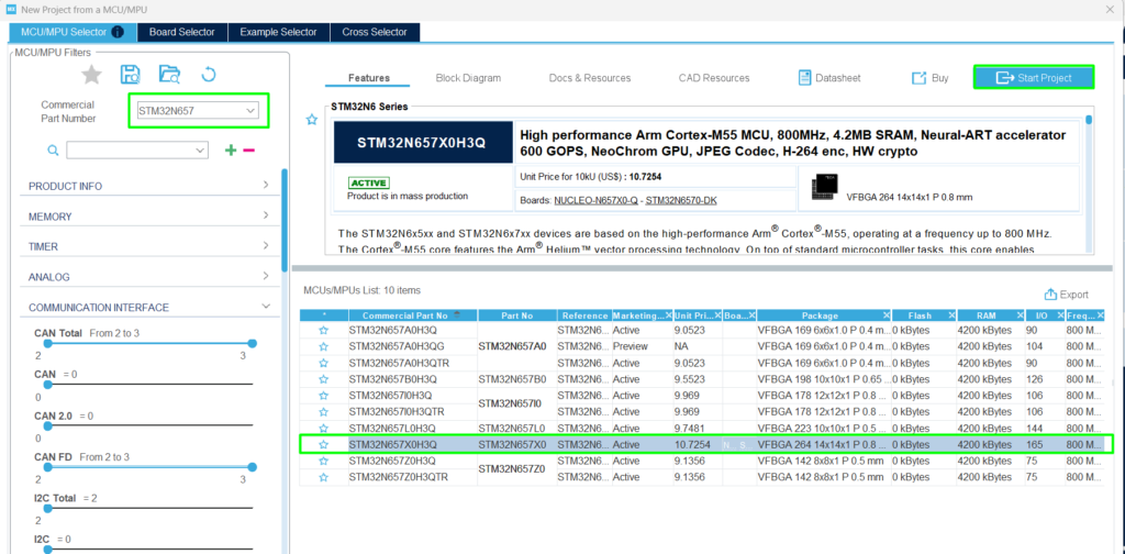
Step 1: Create your CubeMX project
Open CubeMX and create the project using the STM32N67X:
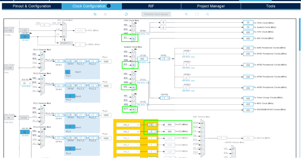
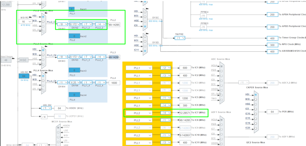
Adjust the clock to run at a higher frequency, go to [Clock Configuration] and change the PLLs to use 400MHz for the main clock branches:
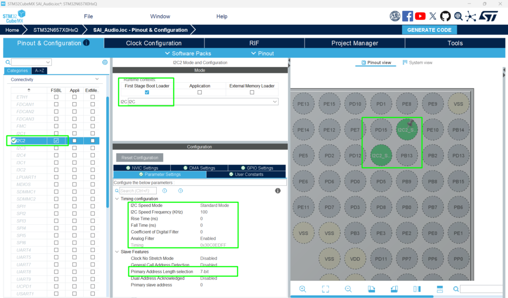
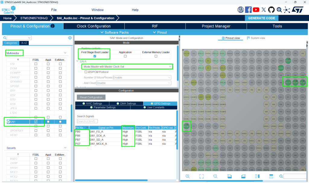
Going back to the [Pinout & Configuration], configure the I2C and SAI, both will be used alongside the codec mentioned:
Hardware pinout overview:
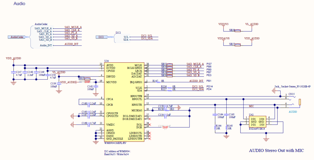
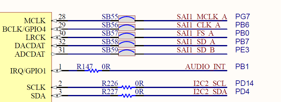
I2C2 -> PD4 [I2C2_SDA] and PD14 [I2C2_SCL]
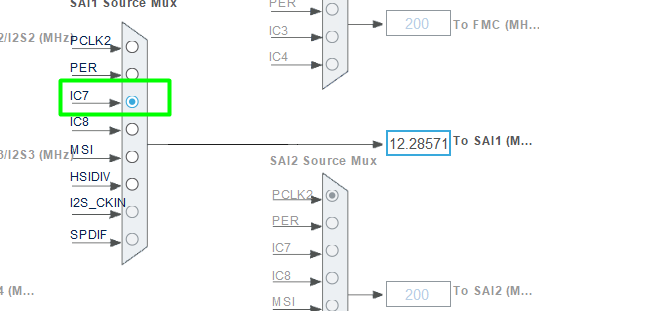
SAI1 Block A:
We will configure the SAI frequency to 12.288 MHz (or as close as possible). This is a strategic frequency for audio applications because it provides flexibility for higher sampling rates and acts as an integer multiple for the entire 48 kHz family.
Why 12.288 MHz?
A master clock (MCLK) of 12.288 MHz is considered “ideal” because it is exactly 256×Fs (where Fs is the sampling frequency) for standard rates:
For 48 kHz: 12.288 MHz=256×Fs
For 24 kHz: 12.288 MHz=512×Fs
For 16 kHz: 12.288 MHz=768×Fs
For 8 kHz: 12.288 MHz=1536×Fs
By using this single master clock, you can cleanly support 8 kHz, 16 kHz, 24 kHz, 32 kHz, and 48 kHz without the need for complex fractional dividers.
Note on Accuracy: If you do not use the “FRACN” feature in the clock configuration, you may see a minor error. At 16 kHz, the error is approximately 0.4 Hz (0.0025%), which is negligible for almost all audio applications.
Go back to the [Clock] tab and select the HSI as entry point for the PLL2 clock
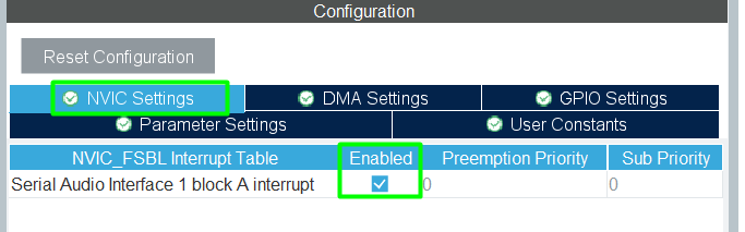
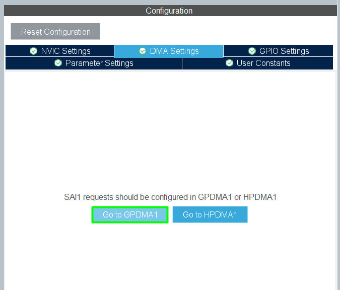
Back to the SAI configuration, enable the IRQ and DMA
GPDMA
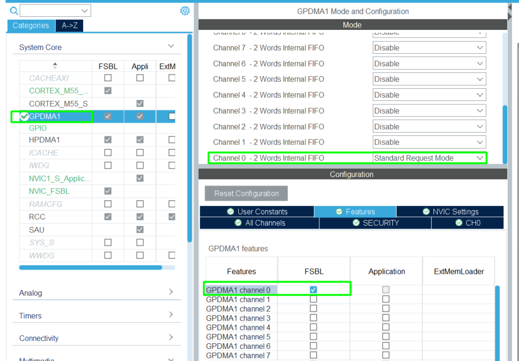
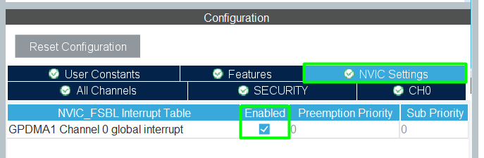
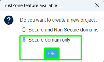
Add the FSBL
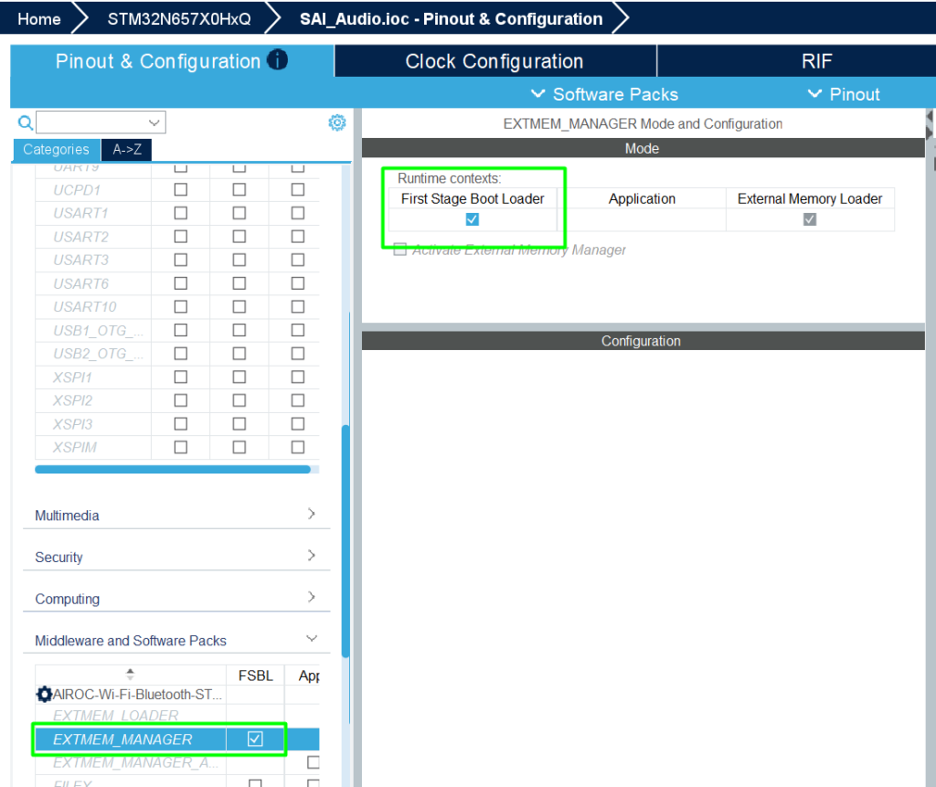
Configure the Project Manager:
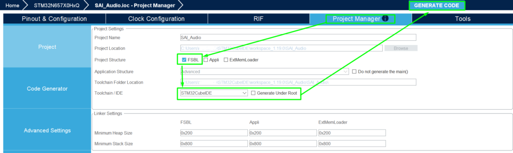
Step 2: CubeIDE, Signature and Build
Within CubeIDE, click File->Open projects from File System and select the project.
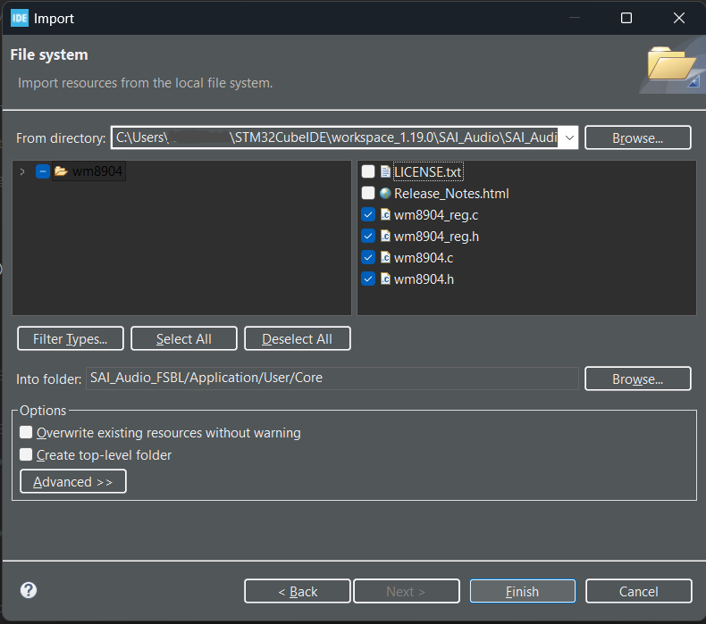
The WM8904 driver is available in your local repository, typically at> C:\Users\%username%\STM32Cube\Repository\STM32Cube_FW_N6_V1.3.0\Drivers\BSP\Components\wm8904
Copy the folder content and incorporate it into your project design. To facilitate, it will be added under User/Core folder:
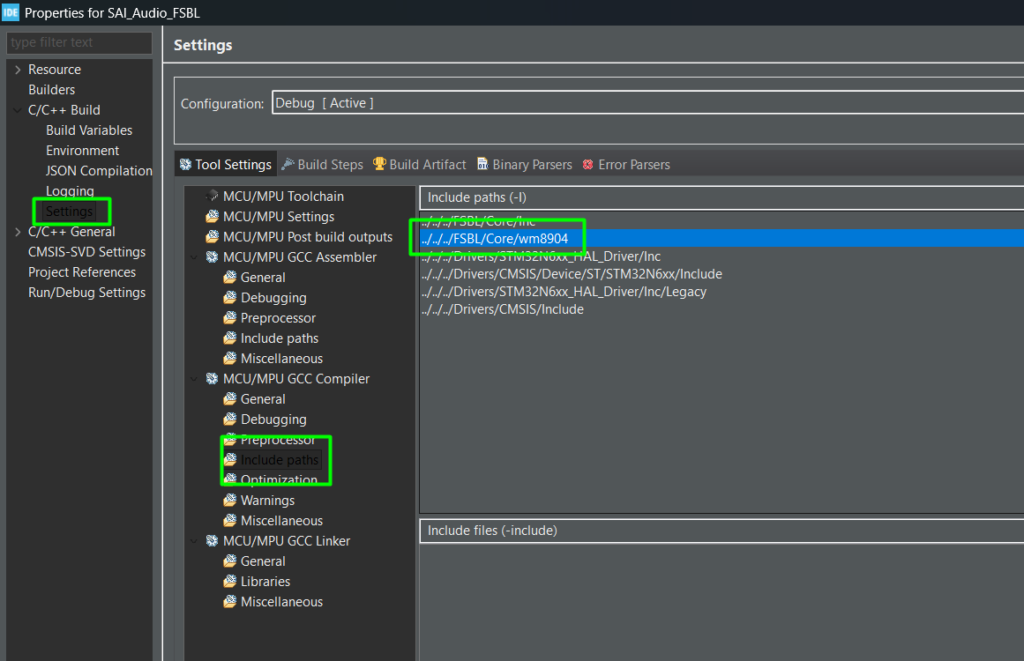
Add the path into the include paths as well:
Make sure your main.c has access to the include files and create the structure to connect the driver with the I2C:
					/* USER CODE BEGIN Includes */
#include "wm8904.h"
/* USER CODE END Includes */

/* USER CODE BEGIN PTD */
/** @defgroup AUDIO_Driver_structure  Audio Driver structure
  * @{
  */
typedef struct
{
  int32_t (*Init)(void *, void *);
  int32_t (*DeInit)(void *);
  int32_t (*ReadID)(void *, uint32_t *);
  int32_t (*Play)(void *);
  int32_t (*Pause)(void *);
  int32_t (*Resume)(void *);
  int32_t (*Stop)(void *, uint32_t);
  int32_t (*SetFrequency)(void *, uint32_t);
  int32_t (*GetFrequency)(void *);
  int32_t (*SetVolume)(void *, uint32_t, uint8_t);
  int32_t (*GetVolume)(void *, uint32_t, uint8_t *);
  int32_t (*SetMute)(void *, uint32_t);
  int32_t (*SetOutputMode)(void *, uint32_t);
  int32_t (*SetResolution)(void *, uint32_t);
  int32_t (*GetResolution)(void *, uint32_t *);
  int32_t (*SetProtocol)(void *, uint32_t);
  int32_t (*GetProtocol)(void *, uint32_t *);
  int32_t (*Reset)(void *);
} AUDIO_Drv_t;
/* USER CODE END PTD */

/* USER CODE BEGIN PV */
static AUDIO_Drv_t *Audio_Drv = NULL;
static void *Audio_CompObj;
extern uint32_t audio_samples_count;
extern const int16_t audio_samples_16k[];
static __IO uint32_t PcmBufferCplt;
/* USER CODE END PV */

/* USER CODE BEGIN PFP */

/**
 * @brief  Write a value in a register of the device through BUS.
 * @param  DevAddr    Device address on Bus.
 * @param  MemAddSize Size of internal memory address
 * @param  Reg        The target register address to write
 * @param  pData      The target register value to be written
 * @param  Length     data length in bytes
 * @retval BSP status
 */
static int32_t I2C2_WriteReg(uint16_t DevAddr, uint16_t Reg, uint16_t MemAddSize, uint8_t *pData, uint16_t Length)
{
	if (HAL_I2C_Mem_Write(&hi2c2, DevAddr, Reg, MemAddSize, pData, Length, 1000) == HAL_OK)
	{
		return HAL_OK;
	}

	return HAL_ERROR;
}

/**
 * @brief  Read a register of the device through BUS
 * @param  DevAddr    Device address on BUS
 * @param  MemAddSize Size of internal memory address
 * @param  Reg        The target register address to read
 * @param  pData      The target register value to be read
 * @param  Length     data length in bytes
 * @retval BSP status
 */
static int32_t I2C2_ReadReg(uint16_t DevAddr, uint16_t Reg, uint16_t MemAddSize, uint8_t *pData, uint16_t Length)
{
	if (HAL_I2C_Mem_Read(&hi2c2, DevAddr, Reg, MemAddSize, pData, Length, 1000) == HAL_OK)
	{
		return HAL_OK;
	}

	return HAL_ERROR;
}


/**
 * @brief  Initializes I2C HAL.
 * @retval HAL status
 */
int32_t WM8904_I2C2_Init(void)
{
	int32_t ret = HAL_OK;
	if (HAL_I2C_GetState(&hi2c2) == HAL_I2C_STATE_RESET)
	{
		MX_I2C2_Init();
	}
	return ret;
}

/**
 * @brief  DeInitializes I2C HAL.
 * @retval HAL status
 */
int32_t WM8904_I2C2_DeInit(void)
{
	int32_t ret = HAL_OK;
	/* Init the I2C */
	if (HAL_I2C_DeInit(&hi2c2) != HAL_OK)
	{
		ret = HAL_ERROR;
	}
	return ret;
}

/**
 * @brief  Write a 8bit value in a register of the device through BUS.
 * @param  DevAddr Device address on Bus.
 * @param  Reg    The target register address to write
 * @param  pData  The target register value to be written
 * @param  Length buffer size to be written
 * @retval HAL status
 */
int32_t WM8904_I2C2_WriteReg(uint16_t DevAddr, uint16_t Reg, uint8_t *pData, uint16_t Length)
{
	int32_t ret;
#if defined(BSP_USE_CMSIS_OS)
	/* Get semaphore to prevent multiple I2C access */
	osSemaphoreWait(BspI2cSemaphore, osWaitForever);
#endif /* BSP_USE_CMSIS_OS */
	if (I2C2_WriteReg(DevAddr, Reg, I2C_MEMADD_SIZE_8BIT, pData, Length) == 0)
	{
		ret = HAL_OK;
	}
	else
	{
		ret = HAL_I2C_GetError(&hi2c2);
	}
#if defined(BSP_USE_CMSIS_OS)
	/* Release semaphore to prevent multiple I2C access */
	osSemaphoreRelease(BspI2cSemaphore);
#endif /* BSP_USE_CMSIS_OS */
	return ret;
}

/**
 * @brief  Read a 8bit register of the device through BUS
 * @param  DevAddr Device address on BUS
 * @param  Reg     The target register address to read
 * @param  pData   Pointer to data buffer
 * @param  Length  Length of the data
 * @retval HAL status
 */
int32_t WM8904_I2C2_ReadReg(uint16_t DevAddr, uint16_t Reg, uint8_t *pData, uint16_t Length)
{
	int32_t ret;
#if defined(BSP_USE_CMSIS_OS)
	/* Get semaphore to prevent multiple I2C access */
	osSemaphoreWait(BspI2cSemaphore, osWaitForever);
#endif /* BSP_USE_CMSIS_OS */
	if (I2C2_ReadReg(DevAddr, Reg, I2C_MEMADD_SIZE_8BIT, pData, Length) == 0)
	{
		ret = HAL_OK;
	}
	else
	{
		ret = HAL_I2C_GetError(&hi2c2);
	}
#if defined(BSP_USE_CMSIS_OS)
	/* Release semaphore to prevent multiple I2C access */
	osSemaphoreRelease(BspI2cSemaphore);
#endif /* BSP_USE_CMSIS_OS */
	return ret;
}

/**
  * @brief  Delay function
  * @retval Tick value
  */
int32_t WM8904_GetTick(void)
{
  return (int32_t)HAL_GetTick();
}
/**
 * @brief  Probe the WM8904 audio codec.
 * @param  None
 * @retval None
 */
static void WM8904_Probe(void)
{
	WM8904_IO_t              IOCtx;
	uint32_t                 wm8904_id;
	static WM8904_Object_t   WM8904Obj;

	/* Configure the audio driver */
	  IOCtx.Address     = 0x34U;
	  IOCtx.Init        = WM8904_I2C2_Init;
	  IOCtx.DeInit      = WM8904_I2C2_DeInit;
	  IOCtx.ReadReg     = WM8904_I2C2_ReadReg;
	  IOCtx.WriteReg    = WM8904_I2C2_WriteReg;
	  IOCtx.GetTick     = WM8904_GetTick;


	if (WM8904_RegisterBusIO(&WM8904Obj, &IOCtx) != WM8904_OK)
	{
		Error_Handler();
	}
	else if (WM8904_ReadID(&WM8904Obj, &wm8904_id) != WM8904_OK)
	{
		Error_Handler();
	}
	else if ((wm8904_id & WM8904_ID_MASK) != WM8904_ID)
	{
		Error_Handler();
	}
	else
	{
		Audio_Drv = (AUDIO_Drv_t *) &WM8904_Driver;
		Audio_CompObj = &WM8904Obj;
	}
}

/* USER CODE END PFP */

  /* USER CODE BEGIN 1 */
	WM8904_Init_t codec_init;
	uint32_t PlaybackStarted = 0;
	uint8_t i = 0;
  /* USER CODE END 1 */

/* USER CODE BEGIN 2 */
	WM8904_Probe();
	/* Initialize audio codec */

	codec_init.InputDevice  = WM8904_IN_NONE;
	codec_init.OutputDevice = WM8904_OUT_HEADPHONE;
	codec_init.Resolution   = WM8904_RESOLUTION_16B;
	codec_init.Frequency    = WM8904_FREQUENCY_16K;
	codec_init.Volume       = 80U;
	if (Audio_Drv->Init(Audio_CompObj, &codec_init) < 0)
	{
		Error_Handler();
	}
	if (Audio_Drv->Play(Audio_CompObj) != 0)
	{
		Error_Handler();
	}
  /* USER CODE END 2 */

/* USER CODE BEGIN 3 */
		if(PlaybackStarted == 0)
		{
			if (HAL_OK != HAL_SAI_Transmit_DMA(&hsai_BlockA1, (uint8_t *) &audio_samples_16k[0+(i*audio_samples_count/16)], audio_samples_count/16))
			{
				Error_Handler();
			}
			PlaybackStarted = 1;
		}
		if(PcmBufferCplt == 1)
		{
			PcmBufferCplt = 0;
			PlaybackStarted = 0;
			i++;
			if(i >= 15)
				i = 0;
		}
	}
  /* USER CODE END 3 */

/* USER CODE BEGIN 4 */
void HAL_SAI_TxCpltCallback(SAI_HandleTypeDef *hsai)
{
	PcmBufferCplt = 1;
	HAL_SAI_DMAStop(&hsai_BlockA1);
}
/* USER CODE END 4 */
Depending on your audio file size, you might need to adjust the linker script.
Step 3: Debugging
After building, simply enter in debug mode as you would with any other STM32, just make sure that before connecting the USB cable, make sure that your BOOT jumpers/Switches are like this (DEV BOOT MODE):
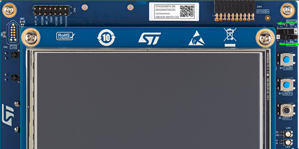
Also, make sure you are using a USB C cable on both sides, as this board is power hungry and will demand more than 500mA. And now that you have, you are free to connect the USB cable
grab your head phone and enjoy your audio on repeat.
6. Conclusion
This article walked through a minimal, yet complete audio playback example on STM32N6-DK:
Audio Preparation
Using ffmpeg to convert input.mp4 into a 16 kHz, mono, 16‑bit PCM WAV (output_mono.wav).
Generating a C file with the raw PCM data (audio_samples_16k[]) after stripping the 44‑byte WAV header.
Understanding the WAV Format
Reviewing the WAV header structure and how it could be validated on STM32.
Clarifying that, for this demo, the header is used only offline and not parsed at runtime.
SAI & Codec Configuration
Configuring SAI1_Block_A as master transmitter, 16‑bit, mono, 16 kHz.
Using DMA for efficient sample transfer.
Relying on WM8904 codec initialization via BSP/I2C.
DMA Playback
Playing the entire PCM content via DMA in successive chunks.
Using a simple state machine in the main loop with HAL_SAI_TxCpltCallback() to chain transfers.
This architecture is deliberately simple and is an excellent first step for:
Voice prompts from flash
Simple sound effects in GUI demos
Educational purposes for understanding SAI + DMA audio pipelines
From here, you can enhance the design by:
Loading WAV files from SD card or external flash and parsing their headers at runtime.
Implementing stereo playback (two channels).
Adding volume control, mute, or simple user interface elements (buttons, touchscreen).
Using double-buffering or circular DMA for continuous streaming with minimal CPU intervention.
Happy Coding 🙂