STM32 Audio
Learn to interface MEMS microphones with STM32U5 using the MDF peripheral. Discover PDM vs PCM, Sinc filters, and Sound Activity Detection (SAD) configuration.
Abstract
Digital audio acquisition in low-power embedded systems is a critical skill for modern IoT development. This article explores the interface between Micro-Electro-Mechanical Systems (MEMS) microphones and the STM32U5 microcontroller using the Multi-function Digital Filter (MDF). We will dissect the signal processing chain, from raw PDM bitstreams to usable audio data, and demonstrate a practical implementation of Sound Activity Detection (SAD) to wake a system from Stop mode.
1. Introduction
In the realm of embedded audio, the days of relying solely on bulky analog microphones and external ADCs are fading. Digital MEMS microphones offer superior immunity to RF interference and simplified routing. However, they introduce a new challenge: they don’t output standard analog voltages or friendly byte-aligned audio samples. Instead, they output a high-frequency, 1-bit stream known as PDM.
To utilize this data, modern microcontrollers like the STM32U5 series employ advanced peripherals like the MDF (Multi-function Digital Filter). This guide will walk you through the theory of digital audio and provide a hands-on configuration guide for building a low-power Sound Activity Detector.
2. Prerequisites
To follow this tutorial, you will need:
- Evaluation Board: STM32U585-IOT | Product – STMicroelectronics
- ST software: STM32CubeMX, STM32CubeIDE, STM32CubeProg
At a high level, the project will:
Initialize clocks and peripherals (ADF, DMA, Clock, GPIO, etc.).
Linked List
Summary
- Hardware Focus: STM32U585xx (B-U585I-IOT02A) and MP23DB01 Digital MEMS Mic.
- Core Concepts: PDM vs. PCM audio formats, MEMS transduction, and Digital Filtering.
- Peripheral: STM32 MDF (Multi-function Digital Filter) / ADF (Audio Digital Filter).
- Application: Configuring clocks, SINC filters, and Sound Activity Detection (SAD) to toggle LEDs upon noise detection while optimizing power consumption.
3. PCM vs. PDM: Understanding the Data
Before configuring registers, we must understand the signal.
Pulse Code Modulation (PCM)
PCM is the standard format used in WAV files and CDs. It represents the amplitude of a signal at a specific point in time using a multi-bit number (e.g., 16-bit or 24-bit).
- Pros: Easy to process with DSPs and play back on DACs.
- Cons: Requires parallel data lines or complex serial protocols (I2S) if transmitted raw.
Pulse Density Modulation (PDM)
PDM is the native language of digital MEMS microphones. Instead of sending the amplitude value, PDM modulates the density of pulses.
- Logic: A high density of logic ‘1’s represents a high positive amplitude. A high density of logic ‘0’s represents a high negative amplitude. An even mix represents silence (zero crossing).
- Mechanism: It is a 1-bit stream running at a very high frequency (typically 1 MHz to 3 MHz).
- Processing: To convert PDM to usable PCM, the signal must be passed through a decimation filter (typically a Sinc filter) to reduce the sample rate and increase the bit-depth.
4. How a MEMS Microphone Works
A MEMS (Micro-Electro-Mechanical Systems) microphone acts as a capacitor. It consists of two plates:
- Backplate: A stiff, perforated stationary plate.
- Diaphragm: A flexible plate that moves with acoustic pressure.
As sound waves hit the diaphragm, the capacitance between the plates changes. An internal ASIC (Application-Specific Integrated Circuit) converts this capacitance change into a PDM bitstream driven by an external clock.
For our hands-on example, we are using the MP23DB01, a high-performance digital MEMS microphone mounted on the MB1551 module of the B-U585I-IOT02A board.
5. The STM32 MDF Peripheral
The STM32U5 introduces the MDF (Multi-function Digital Filter). For audio specifically, we utilize a subset of this functionality often referred to as ADF (Audio Digital Filter).
The MDF/ADF hardware performs the heavy lifting that used to require software libraries or dedicated DSPs:
- Clock Generation: Provides the clock signal to the MEMS mic.
- Bitstream Interface: Reads the incoming PDM data (SPI mode).
- Digital Filtering: Applies Sinc filters (Sinc4 or Sinc5) to decimate the PDM stream into PCM audio.
- Sound Activity Detector (SAD): A low-power hardware block that monitors signal levels and triggers interrupts/wakeups without waking the main CPU core.
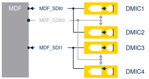
For Microphones, this is the usual hardware settings for 1, 2 or 4 mics.
It is worth mentioning that the MDF is a peripheral designed to interface directly with external Sigma-Delta modulators. While often associated with audio (ADF), the MDF is a versatile block capable of handling motor control currents and metering applications as well.
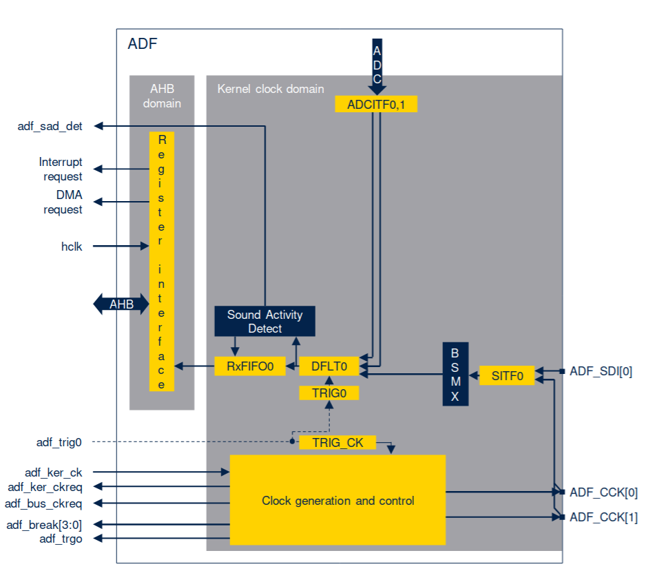
1. Architecture: MDF vs. ADF
It is interesting to distinguish between the two instances of this IP found in the STM32U5:
- MDF (Main Domain): A powerhouse with 6 flexible Digital Filters (DFLT) and 6 Serial Interfaces (SITF). It supports advanced features like a full Bitstream Matrix (BSMX) to route any input to any filter, and auxiliary filters for “Out of Limit” detection (useful for motor control protection).
- ADF (SmartRun Domain): A low-power subset optimized specifically for audio. It features 1 Serial Interface and 1 Digital Filter but uniquely includes the Sound Activity Detector (SAD). Because it resides in the SmartRun domain, the ADF can operate autonomously in STOP 2 mode, allowing the rest of the MCU to sleep while it listens for wake-words or acoustic events.
2. The Digital Signal Processing Chain
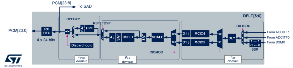
The “magic” of converting a 1-bit PDM stream into high-fidelity 24-bit PCM audio happens inside the DFLT (Digital Filter) block. Unlike simple decimation, the MDF employs a configurable 7-stage pipeline:
- SITF (Serial Interface): Captures data via SPI (rising/falling edge) or Manchester formats. It includes clock absence detection to flag hardware failures.
- CIC Filter (Cascaded Integrator-Comb): The primary decimation engine.
- Modes: Configurable as Sinc4 or Sinc5 for audio.
- Function: Reduces the high-speed bitstream rate (e.g., 2.048 MHz) to a lower intermediate frequency while expanding bit depth.
- Offset & Gain (SCALE):
- Offset Correction (OEC): Removes DC offsets inherent in some MEMS mics.
- SCALE: Applies coarse gain steps (3dB) to normalize the signal volume before further processing, ensuring the signal uses the full 24-bit dynamic range without saturation.
- Reshape Filter (RSFLT): A critical component for audio quality. This low-pass filter cleans up the “droop” caused by the CIC filter and improves out-of-band noise rejection. It typically performs an additional 4x decimation.
- High-Pass Filter (HPF): A first-order DC blocker. Essential for removing wind noise or low-frequency rumble. Cut-off frequencies are programmable (e.g., 10Hz to 456Hz).
- Integrator (INT): Used for specific MEMS sensors that output the derivative of the signal, converting it back to the base signal.
- FIFO: The final 24-bit samples are stored in a 4-word FIFO, triggerable via DMA or Interrupts.
ST provides an interesting overview via image to explain the processing pipeline, oddly, it was made from right to left. CIC->SCALE->RSFLT->HPF and finally the actual PCM.
3. Sound Activity Detector (SAD) Mechanics
The SAD is not just a simple threshold comparator; it is an intelligent state machine designed to adapt to environmental noise.
Here the block diagram.
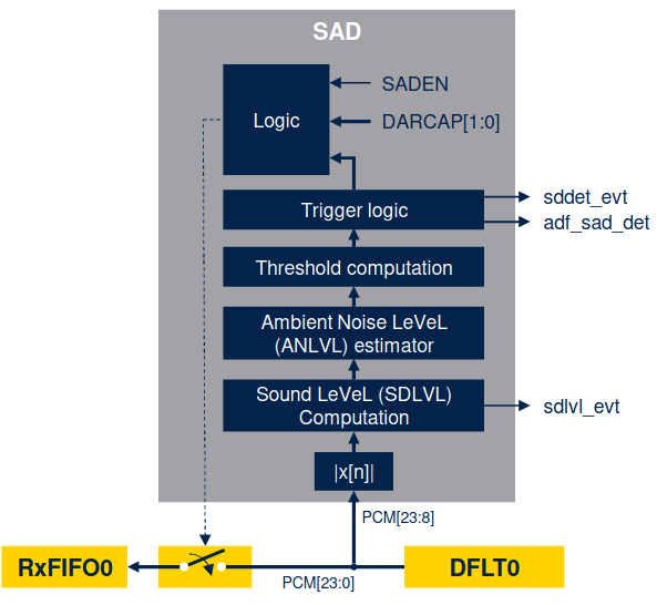
And here is the logic.
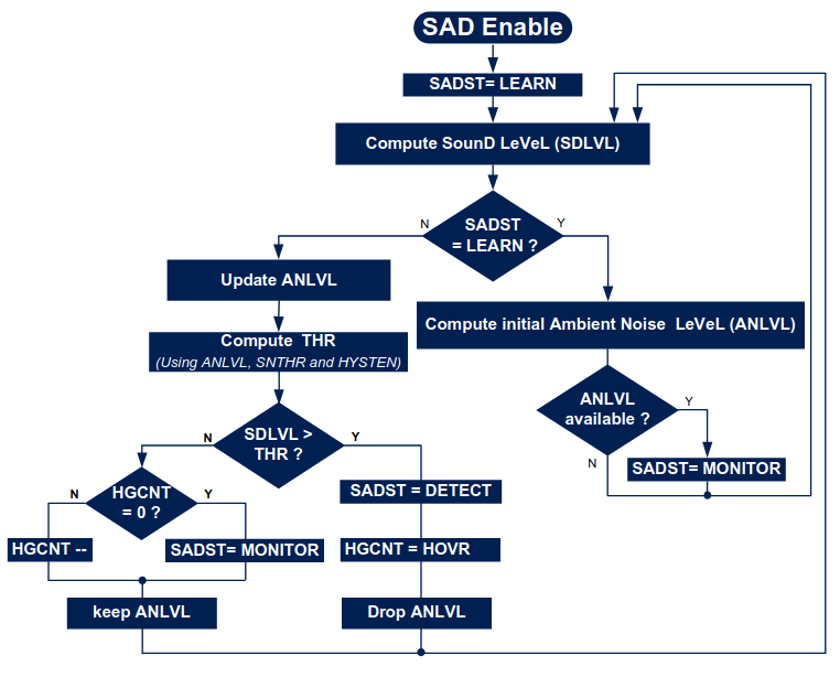
State 1: LEARN: Upon enabling, the SAD analyzes the environment for a fixed number of frames to calculate an initial Ambient Noise Level (ANLVL).
State 2: MONITOR: The peripheral continuously updates the ANLVL to track slowly changing background noise (like a computer fan or AC unit). It compares the instantaneous Sound Level (SDLVL) against a dynamic threshold (Ambient Noise + User Defined Guard Band).
State 3: DETECT: If SDLVL > Threshold, the SAD triggers a “Detect” event (waking the MCU) and enters a “Hangover” period to ensure it doesn’t oscillate rapidly between states.
6. Hands On - STM32 Audio Sound Detector
We will configure the ADF_AudioSoundDetector example. The goal is to detect sound activity, wake the MCU from Stop mode, and toggle a generic LED.
1. Hardware Setup
- Board: B-U585I-IOT02A.
- Mic: MP23DB01 (Onboard).
- Pins:
- PE9 (ADF1_CCK0): Output Clock to Microphone.
- PE10 (ADF1_SDI0): Input Data from Microphone.
2. Clock Configuration
The MP23DB01 requires a clock between 1 MHz and 3.25 MHz. We need to derive this from the system clock to achieve a standard audio sample rate (e.g., 44.1 kHz).
- System Clock: 160 MHz.
- Audio Clock Target: To achieve 44.1 kHz, the source clock is fine-tuned to ≈11.291 MHz.
- Output Divider: We set the ADF output divider to 4.
Mic Clock=411.291 MHz≈2.82 MHz
This falls perfectly within the mic’s 1-3.25 MHz operational range.
3. Serial Interface Configuration
We configure the ADF Serial Interface (SITF) to capture the data.
- Mode: SPI mode (using internal clock).
- Edge: Rising edge data sampling.
- Stream: The MEMS mic output is PDM, interlaced on the data wire.
4. Filter Configuration (The Decimation)
To convert the high-speed PDM to audio samples, we use Filter 0.
- Filter Type: SINC4 (Good balance of latency and attenuation).
- Oversampling Ratio (OSR): 64.
- Integrator Oversampling: 1.
Calculating the Final Sample Rate:
Fsample=Divider×OSRFclock
Fsample=4×6411.291 MHz=44.1 kHz
5. Sound Activity Detector (SAD) Setup
This is the critical low-power feature. We don’t want to process audio continuously; we only want to wake up when noise happens.
- Mode: Ambient Noise Detection.
- Threshold: Set a specific sound level (SDLVL).
- Action: When Sound > Threshold, trigger an interrupt.
- Power Mode: The MCU enters STOP mode. The ADF remains active in a low-power state.
6. Execution Flow
- Initialize HAL: Configure System and GPIOs (PE9/PE10).
- Tune Clocks: Adjust PLLs to generate the audio-specific 11.291 MHz base.
- Start DMA: Initiate ADF conversion in circular mode. Note: In this example, we aren’t piping audio to a codec, just analyzing it.
- Enter Stop: The CPU sleeps.
- Wakeup: When you clap or speak, the SAD triggers an interrupt.
- Feedback: The Green LED toggles.
Note: If the Red LED turns on, the initialization failed or a clock synchronization error occurred.
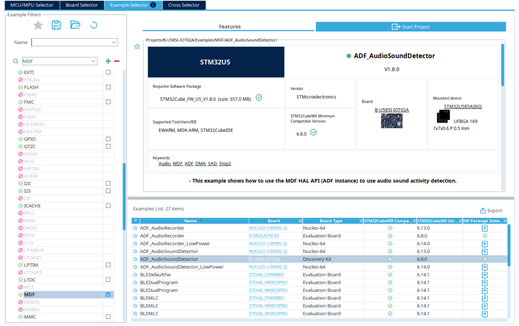
Now that all the main steps are known, create a new project from the Example Selector, filtering by MDF and locating the ADF_AudioSoundDetector.
Create your CubeMX project
Now that all the main steps are known, create a new project from the Example Selector, filtering by MDF and locating the ADF_AudioSoundDetector.
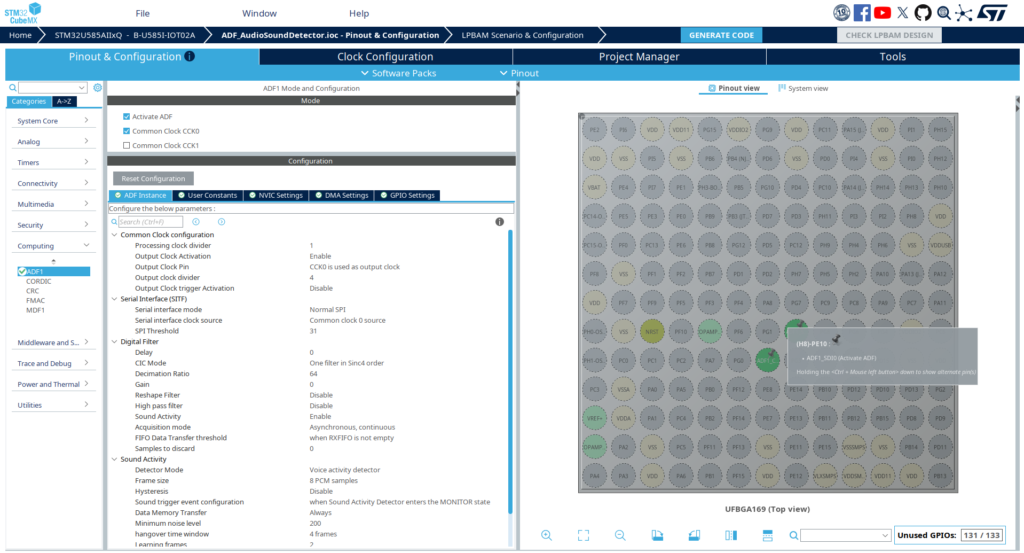
Exploring the main *.ioc file. The ADF configuration is fully set, with the digital filter calculated as well as the proper clock.
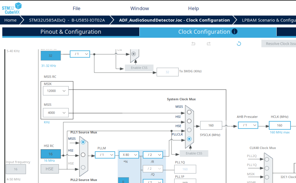
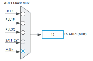
The clock is the other key factor, which can be observed in the Clock Configuration tab. MSIK comes from the MSIS RC and the ADF uses it as base clock.
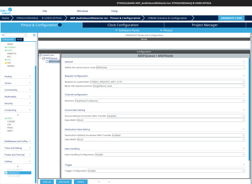
The final relevant portion is that this demo relies on the DMA via Linked List, which might be a bit overwhelming for the first time checking it, but it is basically equivalent to a regular GPDMA or LPDMA use case. Here is the linked list configuration.
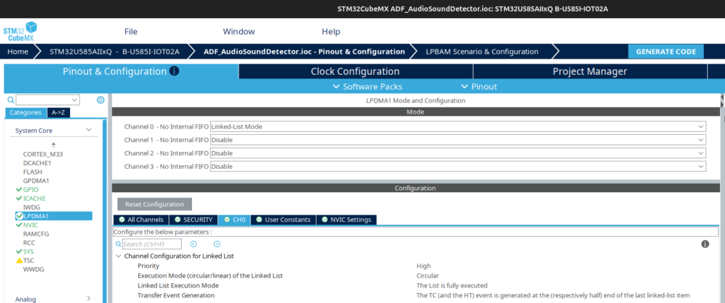
And here is the LPDMA for channel 0, set to work in circular mode and executing the entire list, which as we saw consists of only the ADF.
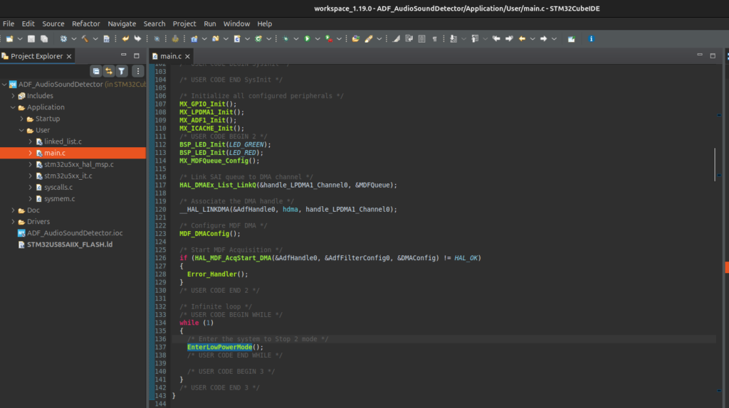
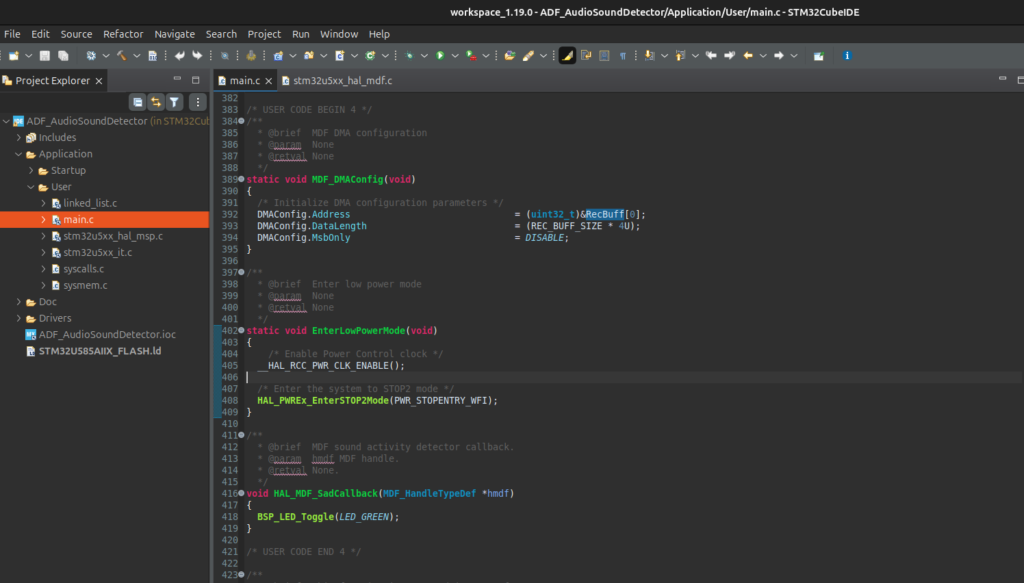
Generate the code and the application will be present upon importing the project into CubeIDE. The code configures the MDF, DMA linked list and then starts the MDF acquisition. The main loop enter in low power mode, STOP2.
The PCM audio is recorded in the RecBuff buffer
7. Beyond Detection: Preparing Audio for Edge AI
Now that we have successfully configured the MDF to capture high-fidelity audio and implemented Sound Activity Detection (SAD) to wake our system efficiently, we face the next challenge: Intelligence.
Detecting that sound happened (SAD) is only step one. Determining what that sound was (e.g., “Marvin”, “Lights On”, or “Glass Break”) requires complex pattern recognition. To achieve this on a microcontroller, we cannot feed raw PCM audio directly into a Neural Network—it is too noisy and high-dimensional. We need to extract features.
The Bridge: Linking MDF to CMSIS-DSP
In our next tutorial phase, we will implement the industry-standard feature extractor for audio AI: Real-Time Mel Spectrograms
We have already documented the deep-dive implementation of this preprocessing stage. Once you have your MDF generating interrupts, head over to our companion article:
STM32U5 Audio Prep for AI: Implementing Real-Time Mel Spectrograms with CMSIS-DSP
This guide picks up exactly where we left off, teaching you how to transform your raw MDF audio streams into the tensor formats required by TensorFlow Lite for Microcontrollers.
Conclusion
The MDF peripheral on the STM32U5 represents a significant leap forward for embedded audio. By offloading the PDM-to-PCM decimation and sound detection to hardware, developers can build responsive, high-fidelity audio applications that sip power. Whether you are building a smart speaker or a glass-break detector, mastering the ADF is your first step.
Happy Coding 🙂