Arduino Basics: KY-001 Temperature Sensor Module
Abstract
Learn how to use the KY-001 Temperature Sensor Module with Arduino. This module typically contains a DS18B20 digital temperature sensor or a simple thermistor (like the 10k NTC thermistor). This tutorial will focus on the more common thermistor implementation often found on the KY-001, which requires reading an Analog Input voltage and converting it to a temperature using the Steinhart-Hart equation (simplified).
1. Introduction
The KY-001, in its simplified form, functions as an analog temperature sensor using a Negative Temperature Coefficient (NTC) thermistor in a voltage divider circuit.
- NTC Thermistor: Its resistance decreases as its temperature increases.
- Voltage Divider: The changing resistance of the thermistor causes a proportional change in the voltage read by the Arduino’s Analog Input Pin.
In this article you’ll learn:
- The relationship between resistance and temperature in an NTC thermistor.
- How to read the thermistor’s voltage using analogRead().
- The steps required to convert the raw Analog-to-Digital Converter (ADC) reading into a physical resistance.
- How to use a simplified conversion formula to calculate temperature in Celsius (C) and Fahrenheit (F).
This project introduces a complex nonlinear analog conversion essential for environmental monitoring.
2. Prerequisites and Hardware Setup
Make sure you have:
- An Arduino Nano or compatible board.
- One KY-001 Temperature Sensor Module (assuming the thermistor version).
- Jumper Wires.
- Arduino IDE
3. Wiring and Setup for Arduino
The KY-001 module requires an analog input pin.
Step 1 – Identify Pins
The module typically has three pins: Signal (S or OUT), VCC (+), and GND (− or GND).
Step 2 – Connect the Module
Wire the module to the Arduino as follows. The signal pin must be connected to one of the Analog Input Pins (A0-A5).
- Connect the GND pin of the KY-001 to the GND pin on the Arduino.
- Connect the VCC pin of the KY-001 to the 5V pin on the Arduino.
- Connect the S / Signal pin of the KY-001 to Arduino Analog Pin A0.
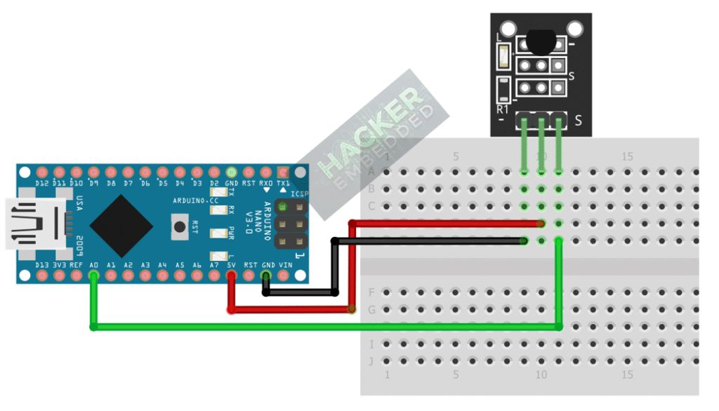
This image was created with Fritzing
Step 3 – Understanding Key Constants
To convert the resistance to temperature, we need constants specific to the thermistor (assuming a standard 10kΩ NTC with a B-parameter of 3950):
- R0=10000 (Resistance at nominal temperature, 10kΩ)
- T0=298.15 (Nominal temperature in Kelvin, 25∘C)
- B=3950 (The B-parameter, characteristic of the material)
- Rseries=10000 (The fixed resistor in the module’s voltage divider circuit)
4. Writing Temperature Conversion Code
The code requires two main calculations:
- ADC Reading to Resistance (R): Uses the voltage divider formula.
- Resistance to Temperature (T): Uses the Steinhart-Hart equation (simplified B-parameter model).
Open main.ino and implement the following code.
					// 1. Hardware Pin
const int THERMISTOR_PIN = A0;

// 2. Thermistor Constants (Standard 10k NTC with 10k series resistor)
const float R_SERIES = 10000.0; // The fixed resistor value in the voltage divider
const float R_NOMINAL = 10000.0; // Resistance at 25C
const float T_NOMINAL = 298.15; // Temperature in Kelvin at 25C (25 + 273.15)
const float B_COEFFICIENT = 3950.0; // The Beta coefficient of the thermistor material

void setup() {
  Serial.begin(9600);
  Serial.println("KY-001 Thermistor Temperature Sensor Ready!");
}

void loop() {
  // --- A. Read and Convert ADC to Resistance ---
  int rawADC = analogRead(THERMISTOR_PIN);

  // Calculate resistance R from voltage divider formula:
  // R = R_SERIES / (1023 / ADC - 1)
  float resistance = R_SERIES / ((1023.0 / rawADC) - 1.0);

  // --- B. Convert Resistance to Temperature (Kelvin) ---
  // Steinhart-Hart simplified B-parameter equation:
  // 1/T = 1/T0 + (1/B) * ln(R/R0)
  float steinhart;
  steinhart = resistance / R_NOMINAL;        // (R / R0)
  steinhart = log(steinhart);                // ln(R / R0)
  steinhart /= B_COEFFICIENT;                // (1/B) * ln(R / R0)
  steinhart += 1.0 / T_NOMINAL;              // 1/T0 + (1/B) * ln(R / R0)
  steinhart = 1.0 / steinhart;               // T (Temperature in Kelvin)

  // --- C. Final Conversion to Celsius and Fahrenheit ---
  float tempC = steinhart - 273.15;          // Convert Kelvin to Celsius
  float tempF = (tempC * 9.0) / 5.0 + 32.0;  // Convert Celsius to Fahrenheit

  // --- D. Print Results ---
  Serial.print("Raw ADC: ");
  Serial.print(rawADC);
  Serial.print(" | Temp C: ");
  Serial.print(tempC, 2); // Print with 2 decimal places
  Serial.print(" | Temp F: ");
  Serial.println(tempF, 2);

  delay(1000);
}
Code Explanation
- Voltage Divider: The formula R = R_SERIES / (1023 / ADC – 1) calculates the thermistor’s resistance based on the ADC reading and the fixed 10kΩ series resistor.
- Steinhart-Hart Model: This is a non-linear equation used to accurately model the resistance-to-temperature relationship of a thermistor. It is done in a step-by-step manner to find the temperature in Kelvin first.
- Temperature Change: If you heat the sensor (e.g., with your finger), the resistance decreases, the ADC reading increases, and the calculated temperature rises.
OPTIONAL
If your KY-001 has the DS18B20, which has the single-bus digital temperature sensor, consider using any digital pin instead and the following code:
#include <OneWire.h>
#include <DallasTemperature.h>
// Data wire is plugged into pin 2 on the Arduino
#define ONE_WIRE_BUS 2
// Setup a oneWire instance to communicate with any OneWire devices (not just Maxim/Dallas temperature ICs)
OneWire oneWire(ONE_WIRE_BUS);
// Pass our oneWire reference to Dallas Temperature.
DallasTemperature sensors(&oneWire);
void setup(void)
{
// start serial port
Serial.begin(9600);
Serial.println("Dallas Temperature IC Control Library Demo");
// Start up the library
sensors.begin(); // IC Default 9 bit. If you have troubles consider upping it 12. Ups the delay giving the IC more time to process the temperature measurement
}
void loop(void)
{
// call sensors.requestTemperatures() to issue a global temperature
// request to all devices on the bus
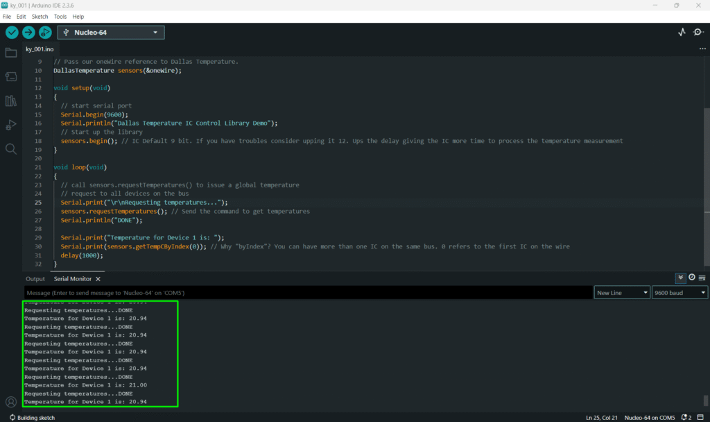
Serial.print("\r\nRequesting temperatures...");
sensors.requestTemperatures(); // Send the command to get temperatures
Serial.println("DONE");
Serial.print("Temperature for Device 1 is: ");
Serial.print(sensors.getTempCByIndex(0)); // Why "byIndex"? You can have more than one IC on the same bus. 0 refers to the first IC on the wire
delay(1000);
}
5. Uploading and Running the Project
Step 1 – Build & Upload
Complete the standard build and upload process.
Step 2 – Test
- Open the Serial Monitor (Tools > Serial Monitor).
- Observe the initial reading (should be close to room temperature, ≈20-25∘C).
- Hold the sensor firmly between your fingers. The ADC reading should increase, and the calculated temperature (C and F) should rise towards body temperature (≈37∘C).
6. Hands-On Lab Recap
You’ve learned:
- The function of an NTC thermistor within a voltage divider.
- The two-step process to convert a raw ADC reading into a physical temperature.
- How to apply the Steinhart-Hart (B-parameter) model for non-linear temperature sensing.
This concludes the comprehensive series on fundamental KY-series modules, providing you with a complete toolkit for basic electronic projects.
7. Common Issues & Fixes
| Issue | Cause | Solution |
|---|---|---|
| ADC is fixed at 0 or 1023. | Wiring error or VCC/GND issue | Check that VCC is 5V and GND is secure. Ensure the signal pin is on an Analog pin. |
| Temperature reading is consistent but incorrect. | Incorrect constants (Rseries or B) used in the code. | Measure the actual series resistor on your module. If the B-coefficient is wrong, the conversion will drift at extreme temperatures. |
| Code doesn't compile (error on log). | Missing Math Library. | Ensure you are using floating-point variables (float) for all math operations and that log() is recognized. |