Arduino Tutorial: KY-009 RGB Full Color LED Module
Abstract
Learn how to use Pulse Width Modulation (PWM) with Arduino digital output pins to interface with the KY-009 RGB Full Color LED SMD Module. This tutorial focuses on independently controlling the Red, Green, and Blue channels to achieve a vast spectrum of colors through analogWrite().
1. Introduction
The KY-009 module is an RGB LED (Red, Green, Blue) housed on a simple breakout board. By controlling the intensity of each primary color, you can generate virtually any color visible on a digital screen. This requires using PWM, making it a key exercise in controlling analog effects with digital microcontrollers.
In this episode, you’ll learn:
- The Common Cathode configuration of the KY-009.
- How to identify and wire the PWM pins on the Arduino.
- How to use analogWrite() for brightness control (color mixing).
- A technique for smooth color transitions (fading).
This project adds advanced visual feedback to your Arduino projects, surpassing the limitations of single-color or bi-color LEDs.
2. Prerequisites
Make sure you have:
- An Arduino Uno or compatible board.
- One KY-009 RGB Full Color LED SMD Module.
- Three 220Ω to 330Ω Resistors (Crucial for current limiting).
- Jumper Wires.
- Arduino IDE
3. Wiring and Setup for Arduino
The KY-009 is a Common Cathode module, meaning the shared ground pin must be connected to GND, and the individual color pins are activated by a HIGH signal (or PWM) via a current-limiting resistor.
Step 1 – Identify Pins
The module typically has four pins: Red (R), Green (G), Blue (B), and Ground (GND).
Step 2 – Connect the Module (Using PWM Pins)
Wire the module to the Arduino using PWM pins for the color channels:
KY-009 Pin | Function | Arduino Connection |
B (Blue) | Blue LED Anode | Digital Pin ~11 (via 100Ω resistor) |
G (Green) | Green LED Anode | Digital Pin ~10 (via 100Ω resistor) |
R (Red) | Red LED Anode | Digital Pin ~9 (via 180Ω resistor) |
– / GND | Common Cathode | GND Pin |
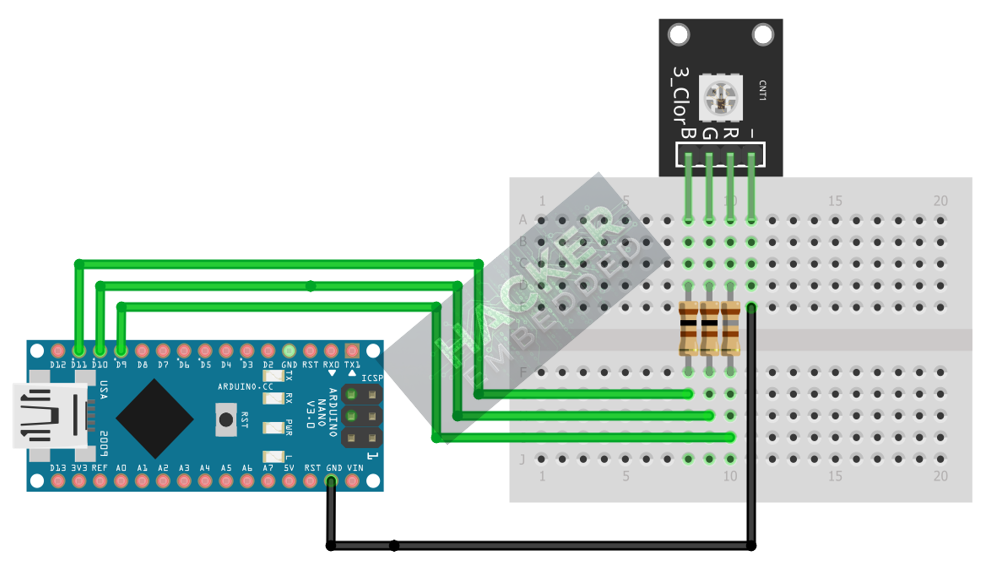
This image was created with Fritzing
Step 3 – Initialize Pin Mode
All three color pins must be initialized as OUTPUT in the setup() function:
pinMode(RED_PIN, OUTPUT);
pinMode(GREEN_PIN, OUTPUT);
pinMode(BLUE_PIN, OUTPUT);
4. Writing Laser Control Code (Morse Code Example)
Open main.ino and implement the following code. This basic code demonstrates setting three distinct static colors: Red, Green, and a custom Purple.
					const int RED_PIN = 9;
const int GREEN_PIN = 10;
const int BLUE_PIN = 11;

void setup() {
  pinMode(RED_PIN, OUTPUT);
  pinMode(GREEN_PIN, OUTPUT);
  pinMode(BLUE_PIN, OUTPUT);
  Serial.begin(9600);
}

void loop() {
  // 1. Display RED (Max Red, Off Green/Blue)
  analogWrite(RED_PIN, 255);
  analogWrite(GREEN_PIN, 0);
  analogWrite(BLUE_PIN, 0);
  delay(2000);

  // 2. Display GREEN
  analogWrite(RED_PIN, 0);
  analogWrite(GREEN_PIN, 255);
  analogWrite(BLUE_PIN, 0);
  delay(2000);

  // 3. Display PURPLE (Custom Mix: Full Red, Half Blue)
  analogWrite(RED_PIN, 255);
  analogWrite(GREEN_PIN, 0);
  analogWrite(BLUE_PIN, 128);
  delay(2000);
}
Code Explanation
- analogWrite(pin, value): This function is used on PWM pins to output a square wave whose duty cycle (ON time) is proportional to the value (0 to 255).
- 0 (OFF): 0% duty cycle.
- 255 (Max Brightness): 100% duty cycle.
- 128 (Half Brightness): ∼50% duty cycle.
5. Smooth Color Transitions (Fading)
To achieve dynamic color mixing and smooth transitions, you must incrementally adjust the PWM values of the primary colors over time. This technique eliminates abrupt changes and is the core of “full color” capability.
					const int RED_PIN = 9;
const int GREEN_PIN = 10;
const int BLUE_PIN = 11;

// Example: Fade Blue from OFF (0) to ON (255)
void fadeBlue() {
  for (int blueValue = 0; blueValue <= 255; blueValue += 1) {
    analogWrite(BLUE_PIN, blueValue);
    delay(5); // Control the speed of the fade
  }
}

// Example: Cross-Fade from Yellow (Red + Green) to Cyan (Green + Blue)
void crossFade() {
  for (int i = 0; i <= 255; i += 1) {
    // Red Dims (255 down to 0)
    analogWrite(RED_PIN, 255 - i);
    // Green Stays ON (255)
    analogWrite(GREEN_PIN, 255);
    // Blue Brightens (0 up to 255)
    analogWrite(BLUE_PIN, i);
    delay(5);
  }
}

void setup() {
  pinMode(RED_PIN, OUTPUT);
  pinMode(GREEN_PIN, OUTPUT);
  pinMode(BLUE_PIN, OUTPUT);
  Serial.begin(9600);
}

void loop() {
  // 1. Display RED (Max Red, Off Green/Blue)
  analogWrite(RED_PIN, 255);
  analogWrite(GREEN_PIN, 0);
  analogWrite(BLUE_PIN, 0);
  delay(2000);

  // 2. Display GREEN
  analogWrite(RED_PIN, 0);
  analogWrite(GREEN_PIN, 255);
  analogWrite(BLUE_PIN, 0);
  delay(2000);

  // 3. Display PURPLE (Custom Mix: Full Red, Half Blue)
  analogWrite(RED_PIN, 255);
  analogWrite(GREEN_PIN, 0);
  analogWrite(BLUE_PIN, 128);
  delay(2000);

  crossFade();
  delay(2000);

  fadeBlue();
  delay(2000);
}
Tip: Using nested or sequence-based loops is the standard method for creating the 0→255 and 255→0 transitions required for continuous color cycling.
6. Uploading and Running the Project
Step 1 – Build
Click the Verify button (checkmark icon) in the Arduino IDE to compile the sketch.
Step 2 – Upload
- Connect your Arduino board via USB.
- Select the correct board and COM port.
- Click the Upload (arrow icon) button.
Step 3 – Test
- Run the code from Section 4. The LED should cycle between three colors: Bright Red, Bright Green, and Purple.
- If you implemented the crossFade() function (Section 5) in your loop(), the LED should transition smoothly from Yellow to Cyan, demonstrating true color mixing via PWM.
7. Hands-On Lab Recap
You’ve learned:
- How to use the Common Cathode
- The critical role of PWM (Pulse Width Modulation) in analog control.
- How to use analogWrite() to set individual brightness (0-255).
- How to mix primary colors (R, G, B) to generate a full spectrum of colors.
This skill is fundamental for visual effects and status indicators in any project
8. Common Issues & Fixes
| Issue | Cause | Solution |
|---|---|---|
| Only one color works, or LED doesn't light up. | Missing or incorrectly valued current-limiting resistors. | Ensure 220Ω to 330Ω resistors are placed on each color pin. |
| The LED only displays ON/OFF colors (no mixing). | Using digitalWrite() instead of analogWrite(). | Replace digitalWrite() with analogWrite() and use values between 0 and 255. |
| Code compiles but no output. | Pin assignment error or using non-PWM pins. | Ensure the color pins (R, G, B) are wired to the PWM pins on the Arduino (∼ marks next to pin numbers like 3, 5, 6, 9, 10, 11). |

