Arduino Tutorial: KY-010 Photo Interrupter Module
Abstract
Learn how to use the KY-010 Photo Interrupter Module with Arduino. This module is a non-contact switch that detects when an opaque object passes between its emitter (IR LED) and detector (phototransistor). This tutorial focuses on configuring a digital input pin to read the sensor’s ON/OFF state, making it ideal for speed counting, edge detection, and simple limit switching.
1. Introduction
The KY-010 is also known as an optical slot sensor or optical end-stop. It operates based on two components separated by a small gap:
- IR Emitter: An LED that constantly transmits an invisible infrared beam across the slot.
- Phototransistor Detector: A transistor that conducts electricity when it receives the IR beam.
When an object interrupts the beam, the phototransistor turns OFF, causing the signal pin to change state (e.g., from HIGH to LOW).
In this episode, you’ll learn:
- The principle of photo-interruption.
- How to safely wire the module as a digital input.
- How to read the switched state using digitalRead().
- How to use the sensor to implement a simple event counter.
This project provides a reliable, non-mechanical method for digital switching.
2. Prerequisites
Make sure you have:
- An Arduino Uno or compatible board.
- One KY-010 Photo Interrupter Module.
- One thin, opaque object (e.g., a piece of card or paper) for interruption.
- Jumper Wires.
- Arduino IDE
3. Wiring and Setup for Arduino
The KY-010 module is a digital output device.
Step 1 – Identify Pins
The module typically has three pins: Signal (S or OUT), VCC (+), and Ground (− or GND).
Step 2 – Connect the Module
Wire the module to the Arduino as follows. When the IR beam is clear (uninterrupted), the phototransistor is usually ON, causing the signal pin to go LOW. When interrupted, the signal goes HIGH (Active HIGH logic).
- Connect the – / GND pin of the KY-010 to the GND pin on the Arduino.
- Connect the + / VCC pin of the KY-010 to the 5V pin on the Arduino.
- Connect the S / Signal pin of the KY-010 to Arduino Digital Pin 7.
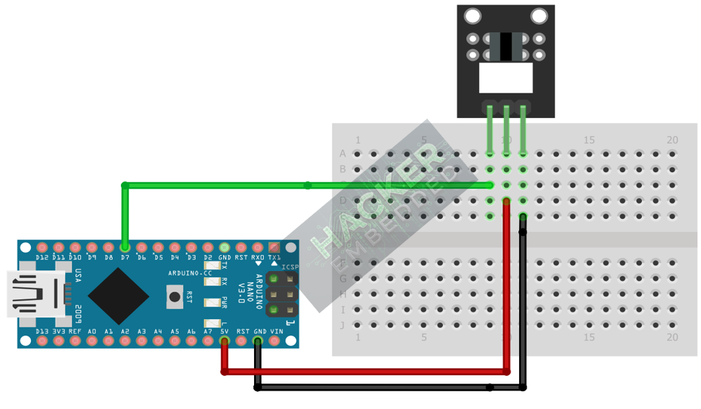
This image was created with Fritzing
Step 3 – Initialize Pin Mode
In the setup() function of your code, set the signal pin as a standard input:
pinMode(7, INPUT);
We will use the on-board LED (Pin 13) as our output indicator.
4. Writing Event Counting Code
Photo interrupters are perfect for counting edges (e.g., the slots on a rotary disk). We will write code to count how many times the beam is interrupted.
					const int INTERRUPTER_PIN = 7;
const int LED_PIN = 13;

// Variables for counting events
int sensorState = 0;        // Current state
int lastSensorState = 0;    // Previous state
long eventCount = 0;        // Total interruptions counted

void setup() {
  pinMode(LED_PIN, OUTPUT);
  pinMode(INTERRUPTER_PIN, INPUT);
  Serial.begin(9600);
  Serial.println("KY-010 Photo Interrupter Counter Ready!");

  // Read the initial state (should be HIGH if active HIGH)
  lastSensorState = digitalRead(INTERRUPTER_PIN);
}

void loop() {
  // Read current sensor state
  sensorState = digitalRead(INTERRUPTER_PIN);

  // Check for the rising edge (transition from LOW to HIGH)
  // Assuming HIGH means the beam is BLOCKED.
  if (sensorState == HIGH && lastSensorState == LOW) {
    eventCount++;
    digitalWrite(LED_PIN, HIGH); // Turn LED ON briefly
    Serial.print("Event Count: ");
    Serial.println(eventCount);
  } else {
    digitalWrite(LED_PIN, LOW);
  }

  // Save the current state for the next loop iteration
  lastSensorState = sensorState;

  // Note: Due to the nature of the sensor, a brief delay (10-50ms) helps stabilize the transition.
  delay(10);
}
Code Explanation
- Active HIGH Logic: When the beam is interrupted (an object is in the slot), the signal output goes HIGH.
- Edge Detection: We check for the specific moment when the signal transitions from LOW (uninterrupted) to HIGH (interrupted). This ensures that a single object passing through the slot is counted only once.
- Speed Counting: For faster applications, you would connect the sensor pin to an Interrupt Pin (like Pin 2 or 3) and use an Interrupt Service Routine (ISR), similar to the KY-040 tutorial, but the polling method here works for moderate speeds.
5. Uploading and Running the Project
Step 1 – Build
Click the Verify button (checkmark icon) in the Arduino IDE to compile the sketch.
Step 2 – Upload
- Connect your Arduino board via USB.
- Select the correct board and COM port.
- Click the Upload (arrow icon) button.
Step 3 – Test
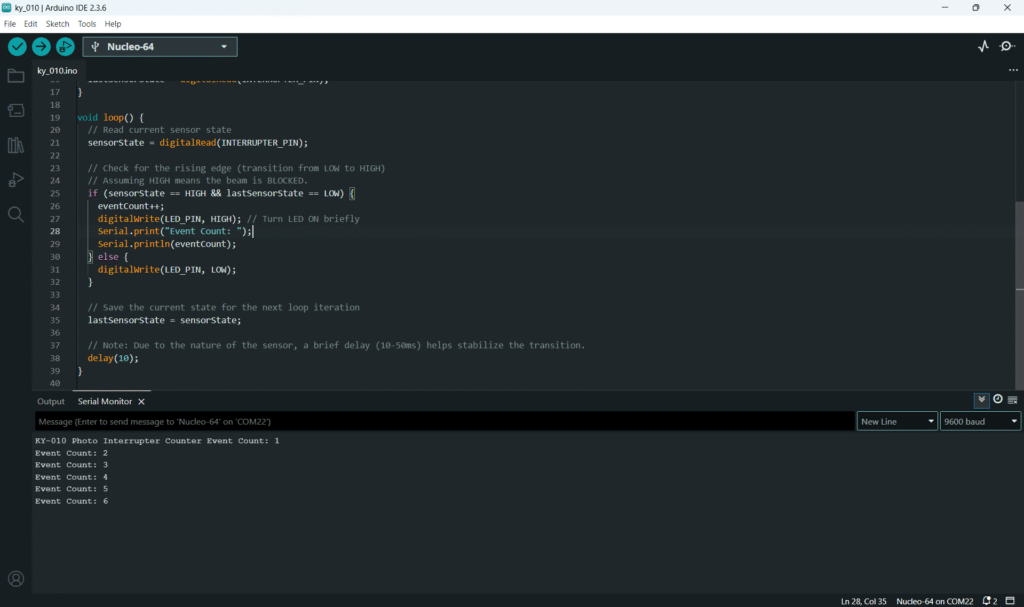
- Open the Serial Monitor (Tools > Serial Monitor).
- The LED should be OFF, and the counter should be stable.
- Pass an opaque object (like a key or card) through the slot of the sensor.
- The Arduino LED should flash briefly, and the Event Count in the Serial Monitor should increment by 1 for each complete pass.
6. Hands-On Lab Recap
You’ve learned:
- The operational principle of the Photo Interrupter (IR beam interruption).
- How to use the edge detection technique (lastSensorState) for accurate event counting.
- A robust, non-mechanical method for digital switching.
This concludes the entire series on fundamental KY-series sensors and I/O types. You now have skills in Digital Input, Digital Output (PWM), and Analog Input across a wide variety of components.
7. Common Issues & Fixes
| Issue | Cause | Solution |
|---|---|---|
| Counter jumps wildly or counts too much. | Signal is bouncing (less common for optical) or state checking logic is flawed. | Ensure you are only counting the edge (LOW → HIGH or HIGH → LOW) and not the sustained state. Increase delay() to 50ms for manual testing. |
| LED is always ON or HIGH when the slot is clear. | Logic Inversion required. | Try reversing the logic in the if statement to count the falling edge (sensorState == LOW && lastSensorState == HIGH). |
| No matter what I do, the sensor reading is fixed. | Sensor slot is blocked by dust/debris or too much ambient light. | Clean the slot. Shield the sensor from direct sunlight or very bright ambient light, as this can saturate the detector. |

