
Arduino Tutorial: KY-011 Two-Color LED Module
Abstract
This tutorial focuses on controlling the KY-011 Two-Color LED Module using Arduino. Learn how to configure Arduino digital output pins and use Pulse Width Modulation (PWM) to achieve color mixing. This is a step-by-step guide on wiring the module and utilizing its Common Cathode configuration to display Red, Green, and Yellow states.
1. Introduction
Following the basics of digital output, we now introduce a component that offers richer visual feedback than a single LED. The KY-011 module, which houses Red and Green LEDs, allows for three distinct visual states (Red, Green, and Yellow/Orange) using just two control pins.
In this episode, you’ll learn:
- How the Common Cathode configuration works.
- How to wire the module safely using current-limiting resistors.
- How to use digitalWrite() for simple ON/OFF control.
- How to use analogWrite() (PWM) to mix colors.
This project adds multi-state signaling to your Arduino applications, essential for indicating status like “Error,” “Ready,” and “Working.”
2. Prerequisites
Make sure you have:
- An Arduino Uno or compatible board.
- One KY-011 Two-Color LED Module.
- Two 220Ω or 330Ω Resistors (Crucial for safety).
- Jumper Wires.
- A Breadboard (Optional).
3. Wiring and Setup for Arduino
The KY-011 module is a Common Cathode device, meaning the shared ground pin must be connected to GND, and the individual color pins must be connected to VCC (HIGH signal) to light up.
Step 1 – Identify Pins and Resistor Needs
The KY-011 operates at a lower voltage (2.0V – 2.5V) than the Arduino’s 5V output. You must use a current-limiting resistor for each color pin.
Step 2 – Set Up Wiring
Wire the module to the Arduino as follows. Note that we use PWM pins (~9 and ~10) for maximum flexibility.
Pin on the KY-011 | Function | Connection on Arduino Uno |
G (Green) | Green LED Anode | Digital Pin ~10 (via a 220Ω resistor) |
R (Red) | Red LED Anode | Digital Pin ~9 (via a 220Ω resistor) |
– or GND | Common Cathode (Ground) | GND Pin |
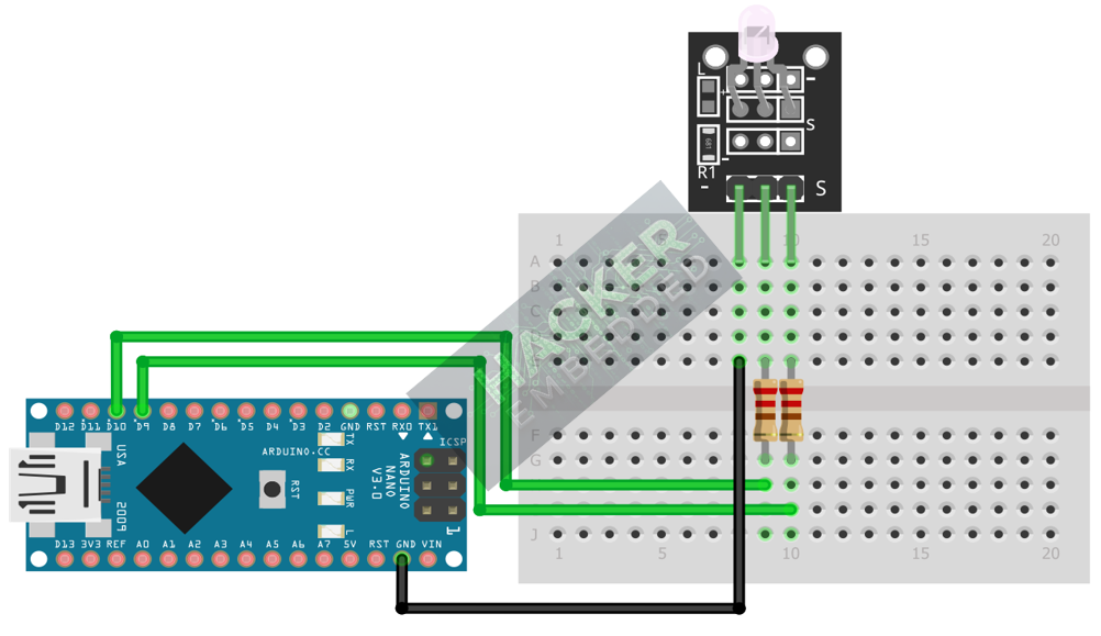
This image was created with Fritzing
Step 3 – Verify Connections
Ensure the – / GND pin is directly connected to Arduino GND. Both R and G pins must pass through a resistor before connecting to the Arduino digital pins.
4. Writing Simple ON/OFF Control Code
Open the Arduino IDE and use the following sketch to alternate between Red and Green colors every three seconds.
					const int RED_PIN = 9;    // Connects to the R pin via resistor
const int GREEN_PIN = 10; // Connects to the G pin via resistor

void setup() {
  // Configure both pins as outputs
  pinMode(RED_PIN, OUTPUT);
  pinMode(GREEN_PIN, OUTPUT);
}

void loop() {
  // 1. Display RED
  digitalWrite(RED_PIN, HIGH);
  digitalWrite(GREEN_PIN, LOW);
  delay(3000);

  // 2. Display GREEN
  digitalWrite(RED_PIN, LOW);
  digitalWrite(GREEN_PIN, HIGH);
  delay(3000);

  // 3. Display YELLOW (Both HIGH)
  digitalWrite(RED_PIN, HIGH);
  digitalWrite(GREEN_PIN, HIGH);
  delay(3000);
}
Code Explanation
- digitalWrite(PIN, HIGH) sends 5V, turning the LED ON.
- digitalWrite(PIN, LOW) sends 0V, turning the LED OFF.
- Turning both pins HIGH displays the combined color, which is Yellow/Orange.
5. Achieving Color Mixing with PWM
Simple digitalWrite() only gives you Red, Green, and Yellow. To create smooth transitions and intermediate shades of orange, we use Pulse Width Modulation (PWM) via the analogWrite() function.
Implementing a Fade Effect
The following code creates a smooth transition from Red to Green and back, passing through all shades of orange/yellow.
					const int RED_PIN = 9;
const int GREEN_PIN = 10;

void setup() {
  pinMode(RED_PIN, OUTPUT);
  pinMode(GREEN_PIN, OUTPUT);
}

void loop() {
  int brightness;

  // 1. Fade from RED to GREEN
  for (brightness = 255; brightness >= 0; brightness -= 1) {
    // Red dims (255 down to 0)
    analogWrite(RED_PIN, brightness);
    // Green brightens (0 up to 255)
    analogWrite(GREEN_PIN, 255 - brightness);
    delay(15);
  }

  // 2. Fade from GREEN to RED
  for (brightness = 0; brightness <= 255; brightness += 1) {
    // Red brightens (0 up to 255)
    analogWrite(RED_PIN, brightness);
    // Green dims (255 down to 0)
    analogWrite(GREEN_PIN, 255 - brightness);
    delay(15);
  }
}
Tip: analogWrite() takes a value between 0 (OFF) and 255 (full brightness), allowing fine control over each LED’s intensity.
6. Uploading and Testing the Project
Step 1 – Connect and Select
- Connect your Arduino board to your computer via USB.
- Select the correct Board (e.g., Arduino Uno) and Port in the Arduino IDE’s Tools menu.
Step 2 – Upload
Click the Upload button (right arrow icon) in the Arduino IDE.
Step 3 – Test
- Observe the KY-011 module.
- It should start with Red, then smoothly fade through Orange and Yellow, and finally reach Green, before fading back.
- The ability to achieve the intermediate colors confirms that your wiring and code are correctly utilizing PWM.
7. Hands-On Lab Recap
You’ve learned:
- The operational principle of the Photo Interrupter (IR beam interruption).
- How to use the edge detection technique (lastSensorState) for accurate event counting.
- A robust, non-mechanical method for digital switching.
This concludes the entire series on fundamental KY-series sensors and I/O types. You now have skills in Digital Input, Digital Output (PWM), and Analog Input across a wide variety of components.
8. Common Issues & Fixes
| Issue | Cause | Solution |
|---|---|---|
| LED instantly burns out. | No current-limiting resistors were used. | ALWAYS use 220Ω or 330Ω resistors on the R and G pins. |
| Only Red and Green are visible, no Yellow/Orange. | The Common Cathode pin (-/GND) is disconnected. | Switch to analogWrite() and ensure you are using PWM pins (~). |
| Only one color turns on. | The Common Cathode pin (-/GND) is disconnected. | Check that the - / GND pin is connected directly to the Arduino GND. |
| The code compiles, but nothing happens. | Pin numbers in the code do not match the physical wiring. | Verify that RED_PIN and GREEN_PIN match the digital pins you wired to. |

