
Arduino Tutorial: KY-016 RGB Full Color LED Module
Abstract
Learn how to use Pulse Width Modulation (PWM) with Arduino digital output pins to interface with the KY-016 RGB Full Color LED Module. This module is a Common Anode type, requiring a different coding logic than the common cathode (KY-009). This tutorial focuses on using analogWrite() with inverted logic to control the Red, Green, and Blue channels for full color mixing.
1. Introduction
The KY-016 is electrically identical to a standard Common Anode RGB LED. This means the common pin is connected to the positive voltage (5V), and the individual color pins are controlled by sinking current to GND. To achieve a color, you must drive the corresponding pin LOW. To control brightness using PWM, we use inverted logic where a PWM value of 0 is full brightness, and 255 is off.
In this episode, you’ll learn:
- The key difference between Common Anode (KY-016) and Common Cathode (KY-009).
- How to apply inverted logic (0=ON,255=OFF) with analogWrite().
- How to wire the module without requiring external resistors (as the KY-016 usually includes them).
- A simple method for cycling through the primary colors.
This project reinforces your understanding of PWM while introducing active-low control.
2. Prerequisites
Make sure you have:
- An Arduino Uno or compatible board.
- One KY-016 RGB Full Color LED Module.
- Jumper Wires.
- Arduino IDE
3. Wiring and Setup for Arduino
The KY-016 is a Common Anode module, meaning the common pin connects to VCC (+5V).
Step 1 – Identify Pins
The module typically has four pins: R (Red), G (Green), B (Blue), and VCC or +.
Step 2 – Connect the Module (Using PWM Pins)
Wire the module to the Arduino, ensuring the color pins go to PWM pins for brightness control.
KY-016 Pin | Function | Arduino Connection |
B (Blue) | Blue LED Cathode | Digital Pin ~9 (PWM) |
G (Green) | Green LED Cathode | Digital Pin ~10 (PWM) |
R (Red) | Red LED Cathode | Digital Pin ~11 (PWM) |
+ / VCC | Common Anode | 5V Pin |
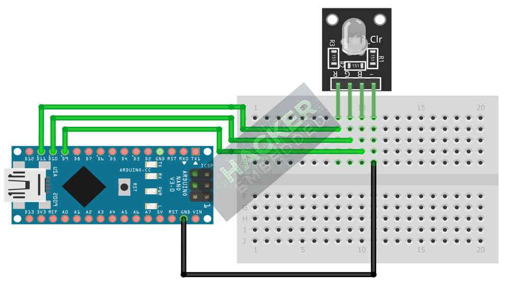
This image was created with Fritzing
Note: Unlike a raw RGB LED, the KY-016 module typically has built-in current-limiting resistors, so external resistors are usually not required.
Step 3 – Initialize Pin Mode
All three color pins must be initialized as OUTPUT in the setup() function:
pinMode(RED_PIN, OUTPUT);
pinMode(GREEN_PIN, OUTPUT);
pinMode(BLUE_PIN, OUTPUT);
4. Writing Common Anode Control Code
Open main.ino and implement the following code. This code demonstrates the inverted logic needed to set the primary colors.
					const int RED_PIN = 11;
const int GREEN_PIN = 10;
const int BLUE_PIN = 9;

// Helper function to set the RGB color using inverted logic
void setRGB(int r, int g, int b) {
  // For Common Anode:
  // 0 = Max Brightness (Full ON)
  // 255 = OFF (Full OFF)
  analogWrite(RED_PIN, 255 - r);
  analogWrite(GREEN_PIN, 255 - g);
  analogWrite(BLUE_PIN, 255 - b);
}

void setup() {
  pinMode(RED_PIN, OUTPUT);
  pinMode(GREEN_PIN, OUTPUT);
  pinMode(BLUE_PIN, OUTPUT);
  Serial.begin(9600);
}

void loop() {
  // 1. Display RED (Max Red: 255, Off Green/Blue: 0)
  setRGB(255, 0, 0);
  delay(1500);

  // 2. Display GREEN
  setRGB(0, 255, 0);
  delay(1500);

  // 3. Display BLUE
  setRGB(0, 0, 255);
  delay(1500);

  // 4. Display WHITE (Full Red, Full Green, Full Blue)
  setRGB(255, 255, 255);
  delay(1500);
}
Code Explanation
- setRGB(r, g, b) Function: This helper function abstracts the inverted logic, allowing you to use intuitive 0-255 values for color brightness.
- 255 – r: This formula performs the inversion. If the user passes r=255 (Max Red), the Arduino writes 255 – 255 = 0 (Full brightness). If the user passes r=0 (Off Red), the Arduino writes 255 – 0 = 255 (Off).
- analogWrite(pin, value): As in the previous RGB tutorial, this function uses PWM to control brightness (duty cycle).
5. Creating a Fading Animation
Because we used the setRGB() helper function, creating a fading animation is straightforward, as the inversion logic is already handled.
					// Example: Fade Red from OFF to ON, then back OFF.
void fadeRed() {
  // Fade IN (0 to 255)
  for (int brightness = 0; brightness <= 255; brightness += 5) {
    setRGB(brightness, 0, 0); // Only Red changes
    delay(20);
  }
  // Fade OUT (255 to 0)
  for (int brightness = 255; brightness >= 0; brightness -= 5) {
    setRGB(brightness, 0, 0); // Only Red changes
    delay(20);
  }
}
Note: Comment the function call fadeRed() inside the loop() to test the smooth Common Anode fading.
6. Uploading and Running the Project
Step 1 – Build
Click the Verify button (checkmark icon) in the Arduino IDE to compile the sketch.
Step 2 – Upload
- Connect your Arduino board via USB.
- Select the correct board and COM port.
- Click the Upload (arrow icon) button.
Step 3 – Test
- If you ran the code from Section 4, the LED should cycle sharply through Red, Green, Blue, and White (a full mix of all three).
- If you ran the fadeRed() function, the LED should smoothly transition from off to bright red and back to off, demonstrating correct PWM control with Common Anode logic.
7. Hands-On Lab Recap
You’ve learned:
- The defining characteristics of a Common Anode
- How to use inverted logic (255−value) to drive Common Anode LEDs with analogWrite().
- How to build a helper function to abstract complex control logic.
This concludes our series on basic digital and PWM output control.
8. Common Issues & Fixes
| Issue | Cause | Solution |
|---|---|---|
| The LED is always off, no matter the code. | Common Anode pin (VCC) is connected to GND instead of 5V. | Move the + / VCC pin to the Arduino's 5V pin. |
| The LED displays the inverse color (e.g., trying to show Red displays Cyan). | Logic is inverted in the code (using 0=OFF,255=ON logic). | Use the helper function setRGB(r, g, b) and ensure the 255−value calculation is performed on the output of analogWrite(). |
| Code compiles but no output. | Pin assignment error or using non-PWM pins. | Ensure the color pins are wired to the PWM pins on the Arduino (∼ marks next to pin numbers: 3, 5, 6, 9, 10, 11). |

