Arduino Tutorial: KY-017 Mercury Tilt Switch Module
Abstract
Learn how to use the KY-017 Mercury Tilt Switch Module. This module contains a glass bulb with a small amount of mercury that completes an electrical circuit when tilted. This tutorial focuses on configuring Arduino digital input pins to detect the change in orientation, acting as a simple and highly accurate digital ON/OFF sensor for tilt detection.
1. Introduction
The KY-017 module utilizes the high conductivity of mercury to reliably close a circuit when the glass bulb changes orientation. Due to the high sensitivity and reliable contact closure of mercury, this switch is often preferred where high stability is needed, though mercury’s toxicity is a concern for modern designs. For this basic tutorial, we will focus on its electrical operation as a digital input sensor.
In this episode, you’ll learn:
- The simple mercury switch principle.
- How to wire the module for digital input using the board’s internal circuitry.
- How to read the tilt state using digitalRead().
- How to use the input to trigger a sustained alert based on orientation.
This project enhances your understanding of orientation sensing using a precise mechanical switch.
2. Prerequisites
Make sure you have:
- An Arduino Uno or compatible board.
- One KY-017 Mercury Tilt Switch Module.
- Jumper Wires.
- Arduino IDE
3. Wiring and Setup for Arduino
The KY-017 module has three pins and operates on 5V. The board often includes a series resistor and an indicator LED.
Step 1 – Identify Pins
The module typically has three pins: Signal (S), VCC (+), and Ground (− or GND).
Step 2 – Connect the Module
Wire the module to the Arduino as follows. The module often has an internal pull-up resistor (or similar circuitry), resulting in the output going LOW when the mercury closes the circuit (tilted).
- Connect the – / GND pin of the KY-017 to the GND pin on the Arduino.
- Connect the + / VCC pin of the KY-017 to the 5V pin on the Arduino.
- Connect the S / Signal pin of the KY-017 to Arduino Digital Pin 7.
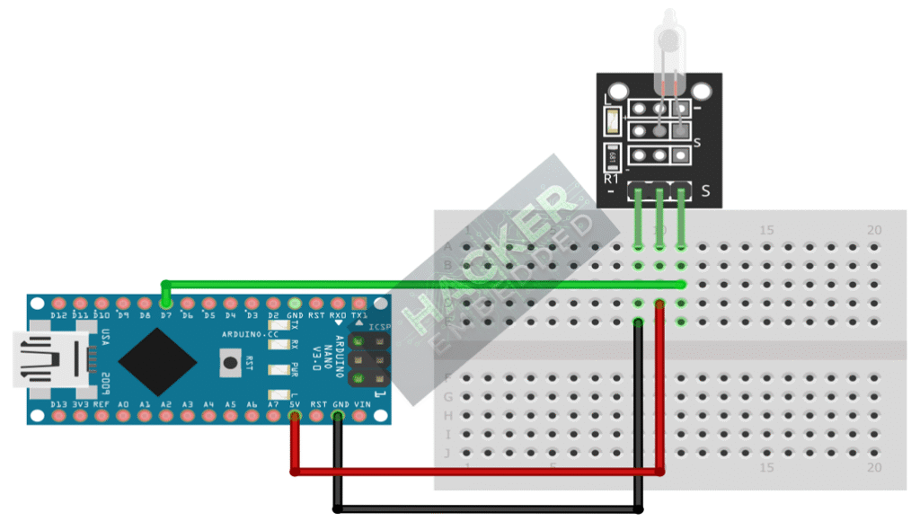
This image was created with Fritzing
Step 3 – Initialize Pin Mode
In the setup() function of your code, set the signal pin as a standard input:
pinMode(7, INPUT);
We will use the on-board LED (Pin 13) as our output indicator, set as OUTPUT.
4. Writing Tilt Detection Code
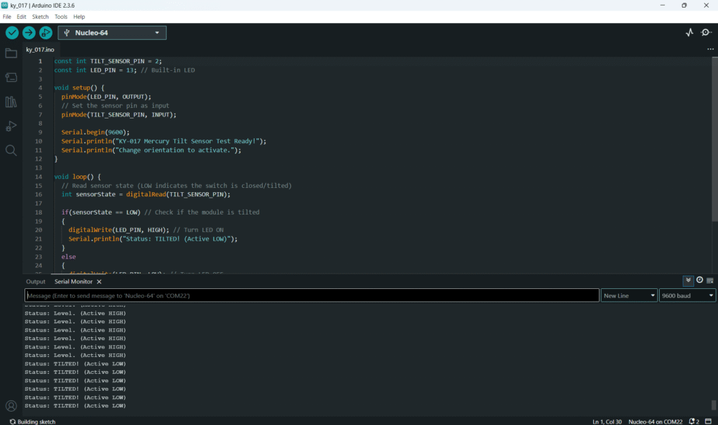
Open main.ino and implement the following code. This code will turn the built-in LED (Pin 13) ON when the mercury switch is activated (tilted, resulting in a LOW signal).
					const int TILT_SENSOR_PIN = 7;
const int LED_PIN = 13; // Built-in LED

void setup() {
  pinMode(LED_PIN, OUTPUT);
  // Set the sensor pin as input
  pinMode(TILT_SENSOR_PIN, INPUT);

  Serial.begin(9600);
  Serial.println("KY-017 Mercury Tilt Sensor Test Ready!");
  Serial.println("Change orientation to activate.");
}

void loop() {
  // Read sensor state (LOW indicates the switch is closed/tilted)
  int sensorState = digitalRead(TILT_SENSOR_PIN);

  if(sensorState == LOW) // Check if the module is tilted
  {
    digitalWrite(LED_PIN, HIGH); // Turn LED ON
    Serial.println("Status: TILTED! (Active LOW)");
  }
  else
  {
    digitalWrite(LED_PIN, LOW); // Turn LED OFF
    Serial.println("Status: Level. (Active HIGH)");
  }

  // A small delay to prevent overwhelming the serial monitor
  delay(100);
}
Code Explanation
- The core logic is the same as other active-low digital switches: The if statement checks for a LOW signal, which indicates the mercury has flowed and closed the circuit.
- Sustained Output: Since the mercury stays in position until re-leveled, this code provides a sustained HIGH output on the LED for the duration of the tilt.
5. Handling State Persistence and Bouncing
The mercury switch is highly reliable and has minimal contact bounce compared to spring or ball-bearing switches. The primary behavior is state persistence—the output is HIGH/LOW until the orientation changes.
Polling vs. Interruption
The Continuous Polling method (Section 4) is perfectly suited for the KY-017, as it’s designed for sustained position monitoring. The low bounce means the small delay(100) outside the if/else block is mainly for Serial Monitor readability, not for debouncing.
Note on Sensitivity
The angle required to trigger the switch is fixed by the size and shape of the mercury tube. You can’t adjust sensitivity in software; you can only monitor the resulting digital change.
6. Uploading and Running the Project
Step 1 – Build
Click the Verify button (checkmark icon) in the Arduino IDE to compile the sketch.
Step 2 – Upload
- Connect your Arduino board via USB.
- Select the correct board and COM port.
- Click the Upload (arrow icon) button.
Step 3 – Test
- Open the Serial Monitor (Tools > Serial Monitor).
- Keep the module flat or level: the LED should be OFF, and the monitor should show “Status: Level.”
- Tilt the KY-017 module past its activation angle: the LED should turn ON, and the monitor should show “Status: TILTED!” continuously until leveled again.
7. Hands-On Lab Recap
You’ve learned:
- How the KY-017 mercury switch translates orientation into a reliable digital signal.
- How to configure Digital pins as input for this type of sustained switch.
- The expected Active LOW behavior due to the module’s integrated circuitry.
- That minimal software debouncing is needed for this highly precise switch type.
This completes your knowledge of simple digital input sensors.
8. Common Issues & Fixes
| Issue | Cause | Solution |
|---|---|---|
| LED is always ON when module is level. | Logic Inversion required. | Try reversing the logic condition: change LOW to HIGH in the if statement. |
| LED never turns ON when tilted. | Wiring error (VCC/GND reversed or signal pin wrong). | Double-check 5V and GND. Ensure the TILT_SENSOR_PIN matches the wire on the Arduino. |
| Output flickers rapidly. | Rare bounce, usually only if shaken aggressively. | Introduce a small stabilizing delay(50); inside the if block before printing/setting output, though typically not needed for the KY-017. |

