Arduino Tutorial: KY-020 Tilt Switch Module
Abstract
Learn how to use the KY-020 Tilt Switch Module, a module containing a mercury-free conductive ball switch. This tutorial focuses on configuring Arduino digital input pins to detect when the module changes its orientation, acting as a simple digital ON/OFF sensor for tilt or orientation change.
1. Introduction
The KY-020 contains a switch that is open when horizontal and closes (connects two terminals) when tilted. Unlike analog sensors, this module provides a simple digital signal, making it perfect for basic orientation alarms, tamper detection, or simple game inputs. It is functionally very similar to the KY-002 Vibration Switch, but is primarily designed for sustained tilt detection rather than momentary vibration.
In this episode, you’ll learn:
- The simple tilt switch principle.
- How to safely wire the module for digital input.
- How to read the tilt state using digitalRead().
- How to use the input to toggle an LED status based on orientation.
This project introduces orientation sensing through a basic digital switch.
2. Prerequisites
Make sure you have:
- An Arduino Uno or compatible board.
- One KY-020 Tilt Switch Module.
- Jumper Wires.
- Arduino IDE
3. Wiring and Setup for Arduino
The KY-020 module has three pins and operates on 5V.
Step 1 – Identify Pins
The module has three pins: Signal (S), VCC (+), and Ground (− or GND).
Step 2 – Connect the Module (Using Digital Input)
Wire the module to the Arduino as follows. The module often contains a pull-up resistor, meaning the output will be HIGH when the switch is open (not tilted) and go LOW when the switch closes (tilted).
- Connect the – / GND pin of the KY-020 to the GND pin on the Arduino.
- Connect the + / VCC pin of the KY-020 to the 5V pin on the Arduino.
- Connect the S / Signal pin of the KY-020 to Arduino Digital Pin 4.
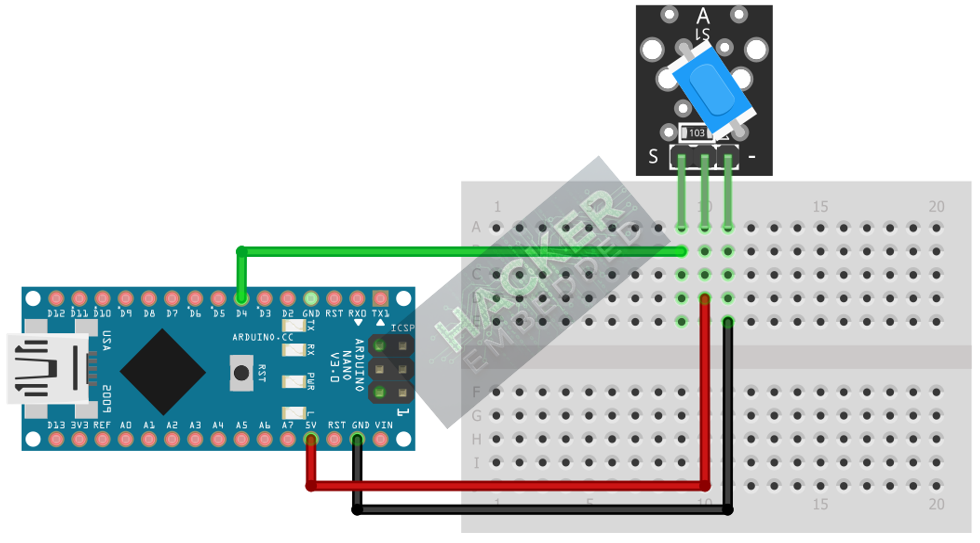
This image was created with Fritzing
Step 3 – Initialize Pin Mode
In the setup() function of your code, set the signal pin as a standard input:
pinMode(4, INPUT);
We will use the on-board LED (Pin 13) as our output indicator, set as OUTPUT.
4. Writing Tilt Detection Code
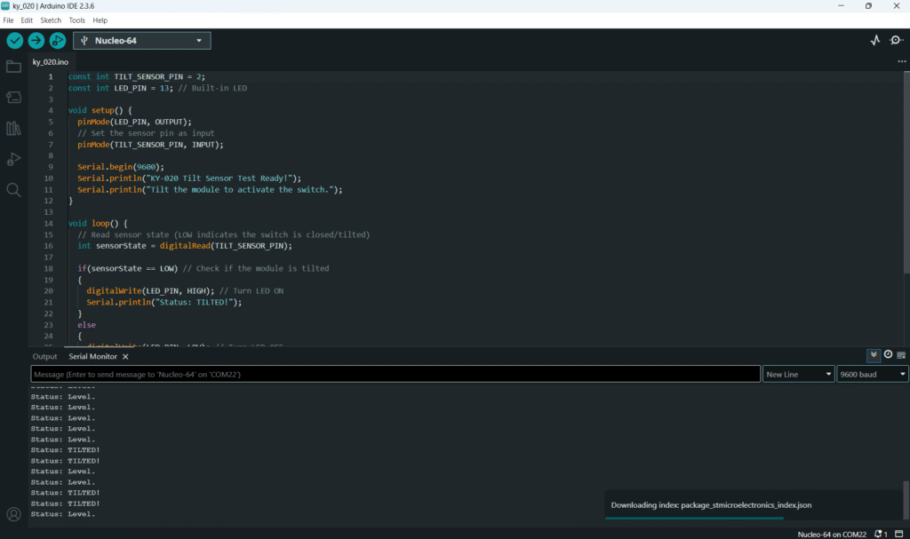
Open main.ino and implement the following code. This code will turn the built-in LED (Pin 13) ON when the tilt switch is activated (tilted, resulting in a LOW signal).
					const int TILT_SENSOR_PIN = 4;
const int LED_PIN = 13; // Built-in LED

void setup() {
  pinMode(LED_PIN, OUTPUT);
  // Set the sensor pin as input
  pinMode(TILT_SENSOR_PIN, INPUT);

  Serial.begin(9600);
  Serial.println("KY-020 Tilt Sensor Test Ready!");
  Serial.println("Tilt the module to activate the switch.");
}

void loop() {
  // Read sensor state (LOW indicates the switch is closed/tilted)
  int sensorState = digitalRead(TILT_SENSOR_PIN);

  if(sensorState == LOW) // Check if the module is tilted
  {
    digitalWrite(LED_PIN, HIGH); // Turn LED ON
    Serial.println("Status: TILTED!");
  }
  else
  {
    digitalWrite(LED_PIN, LOW); // Turn LED OFF
    Serial.println("Status: Level.");
  }

  // A small delay to keep the Serial Monitor readable
  delay(100);
}
Code Explanation
- The if statement checks for a LOW This is the Active LOW state, indicating the internal ball has rolled and closed the circuit to ground (which is often the behavior when a pull-up resistor is used).
- digitalWrite(LED_PIN, HIGH) illuminates the LED to indicate the alert state.
5. Handling State Persistence
Since the KY-020 is a sustained switch (it stays closed as long as it’s tilted), we do not need complex debouncing like with push buttons. However, its digital nature means you must decide whether to continuously poll (as done above) or use interrupts.
Continuous Polling (Current Method)
The code in Section 4 is the Continuous Polling method. It checks the sensor state in every iteration of the loop(). This is simple and effective for the KY-020.
Alternative: Edge Detection (Toggle)
If you wanted the LED to toggle its state (ON → OFF → ON) only when the tilt changes (e.g., tilted once), you would use the complex state management logic shown in the KY-004 tutorial, looking for the transition from HIGH to LOW to trigger the toggle.
Key Difference: For sustained monitoring (e.g., “Is the window tilted now?”), use Continuous Polling (Section 4).
6. Uploading and Running the Project
Step 1 – Build
Click the Verify (checkmark icon) button in the Arduino IDE to compile the sketch.
Step 2 – Upload
- Connect your Arduino board via USB.
- Select the correct board and COM port.
- Click the Upload (arrow icon) button.
Step 3 – Test
- Open the Serial Monitor (Tools > Serial Monitor).
- Keep the module level: the LED should be OFF, and the monitor should show “Status: Level.”
- Tilt the KY-020 module slightly past its activation angle: the LED should turn ON, and the monitor should show “Status: TILTED!” continuously until leveled again.
7. Hands-On Lab Recap
You’ve learned:
- How to translate physical orientation into a digital signal using the KY-020.
- How to configure Digital pins as input for a switch.
- The importance of Active LOW logic when using modules with built-in pull-up resistors.
- The difference between momentary (knock) and sustained (tilt) digital inputs.
This skill is crucial for creating simple security or monitoring systems.
8. Common Issues & Fixes
| Issue | Cause | Solution |
|---|---|---|
| LED is always ON when module is level. | Logic Inversion or faulty module. | Try reversing the logic condition: change LOW to HIGH in the if statement. |
| LED never turns ON when tilted. | Wiring error (VCC/GND reversed or signal pin wrong). | Double-check 5V and GND. Ensure the TILT_SENSOR_PIN matches the wire on the Arduino. |
| Output flickers rapidly when close to the threshold. | Bouncing near the mechanical threshold. | Introduce a small delay(50); outside the if/else block to stabilize readings, or increase the tilt angle required for testing. |

