Arduino Tutorial: KY-023 Dual Axis Joystick Module
Abstract
Learn how to use the KY-023 Dual Axis Joystick Module with Arduino. This module is a compact user input device providing two main forms of control: two analog outputs for the X and Y axes (position) and one digital output for the Z-axis (push button). This tutorial focuses on configuring analog pins to read the joystick’s position and a digital pin to detect the button press.
1. Introduction
The KY-023 is essentially two potentiometers (one for the X-axis, one for the Y-axis) combined with a momentary push button (the Z-axis or switch).
- X and Y Axes (Analog): When the joystick is centered, both axes output a voltage of approximately VCC/2 (raw ADC≈512). Moving the stick along an axis changes that axis’s voltage proportionally, giving you an analog position from 0 to 1023.
- Z-Axis (Digital): Pushing the stick straight down activates a simple switch, providing a digital ON/OFF signal.
In this episode, you’ll learn:
- The principle of positional sensing using potentiometers.
- How to read and map two simultaneous analog inputs (X and Y).
- How to read the digital push button (Z) state.
This project enables the Arduino to receive complex, continuous user input for applications like controlling servos, drone simulation, or navigating menus.
2. Prerequisites
Make sure you have:
- An Arduino Uno or compatible board.
- One KY-023 Dual Axis Joystick Module.
- Jumper Wires.
- Arduino IDE
3. Wiring and Setup for Arduino
The KY-023 module has five pins and requires two analog and one digital input pin.
Step 1 – Identify Pins
The module typically has five pins: GND, VCC, VRx (X-axis Analog), VRy (Y-axis Analog), and SW (Z-axis Digital Switch).
Step 2 – Connect the Module
Wire the module to the Arduino as follows:
- Connect the GND pin of the KY-023 to the GND pin on the Arduino.
- Connect the VCC pin of the KY-023 to the 5V pin on the Arduino.
- Connect the VRx pin to Arduino Analog Pin A0.
- Connect the VRy pin to Arduino Analog Pin A1.
- Connect the SW pin to Arduino Digital Pin 7 (Z-axis switch).

This image was created with Fritzing
Step 3 – Initialize Pin Modes
pinMode(7, INPUT_PULLUP); // Use internal pull-up resistor for the switch
Using INPUT_PULLUP ensures the switch pin is HIGH when the button is OFF (not pressed) and goes LOW when the button is ON (pressed).
4. Writing Joystick Control Code
We will read all three axes (X,Y,Z) and map the analog readings to a simple range of −5 to +5 for easier interpretation.
Open main.ino and implement the following code.
const int SW_PIN = 7; // Digital pin for Z-axis (Switch)
const int VRX_PIN = A0; // Analog pin for X-axis
const int VRY_PIN = A1; // Analog pin for Y-axis
void setup() {
pinMode(SW_PIN, INPUT_PULLUP);
Serial.begin(9600);
Serial.println("KY-023 Joystick Ready!");
}
void loop() {
// --- 1. Read Analog Axes (X and Y) ---
int rawX = analogRead(VRX_PIN);
int rawY = analogRead(VRY_PIN);
// --- 2. Map Analog Readings to a Usable Range (-5 to +5) ---
// The map() function translates a number from one range to another.
// Center is ~512. Max range is 0 to 1023.
int mapX = map(rawX, 0, 1023, -5, 5);
int mapY = map(rawY, 0, 1023, -5, 5);
// Apply a deadzone: set center value to 0 to avoid noise jitter
if (abs(mapX) < 1) mapX = 0;
if (abs(mapY) < 1) mapY = 0;
// --- 3. Read Digital Switch (Z-axis) ---
// Returns LOW when pressed (due to INPUT_PULLUP)
int swState = digitalRead(SW_PIN);
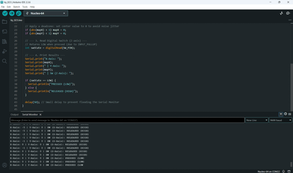
// --- 4. Print Results ---
Serial.print("X-Axis: ");
Serial.print(mapX);
Serial.print(" | Y-Axis: ");
Serial.print(mapY);
Serial.print(" | SW (Z-Axis): ");
if (swState == LOW) {
Serial.println("PRESSED (LOW)");
} else {
Serial.println("RELEASED (HIGH)");
}
delay(50); // Small delay to prevent flooding the Serial Monitor
}
Code Explanation
- INPUT_PULLUP: Used for the switch pin. When the button is open, the pin is pulled HIGH (5V). When closed, it is pulled LOW (GND).
- map(value, fromLow, fromHigh, toLow, toHigh): This crucial function scales the raw sensor data (e.g., 0 to 1023) to a more intuitive range (e.g., −5 to +5).
- Deadzone: The if (abs(mapX) < 1) mapX = 0; line creates a “deadzone” around the center position (≈512). Without this, the reading often jitters between 0 and 1 due to electrical noise or mechanical play.
5. Uploading and Running the Project
Step 1 – Build & Upload
Complete the standard build and upload process.
Step 2 – Test
- Open the Serial Monitor (Tools > Serial Monitor).
- Center Position: Both X and Y axes should read 0 (due to the deadzone).
- Move the Stick:
- Push the stick fully right: X-axis should read +5.
- Push the stick fully left: X-axis should read −5.
- Push the stick fully up: Y-axis should read +5 (or −5, depending on component orientation).
- Press Button: Push the stick straight down. The SW state should switch to PRESSED (LOW).
6. Hands-On Lab Recap
You’ve learned:
- How to simultaneously read multiple analog inputs for X and Y positional data.
- How to use the map() function to scale raw ADC values into a usable range.
- How to read the digital push button (Z-axis) using INPUT_PULLUP.
- The concept of implementing a deadzone for noisy analog inputs.
This concludes the comprehensive series on fundamental KY-series modules.
7. Common Issues & Fixes
| Issue | Cause | Solution |
|---|---|---|
| X or Y axis reading is stuck at 0 or 1023. | Analog pins wired incorrectly. | Check VRx and VRy connections to A0 and A1. Ensure VCC and GND are connected. |
| X and Y readings jump between 0 and 1 when centered. | No Deadzone implemented. | The code already includes a deadzone check (if (abs(mapX) < 1) mapX = 0;). If jitter persists, increase the deadzone value (e.g., < 2). |
| Switch (SW) reads 0 (LOW) when released. | Missing pull-up resistor or wrong pin mode. | Ensure you are using pinMode(SW_PIN, INPUT_PULLUP);. If using INPUT, you need an external pull-up resistor (≈10kΩ). |
| X/Y polarity is reversed (up reads −5, down reads +5). | Module is mounted backwards. | This is normal; simply swap the toLow and toHigh values in the map() function to reverse the direction: map(rawY, 0, 1023, 5, -5);. |

