Arduino Tutorial: KY-025 Reed Switch Module
Abstract
Learn how to use the KY-025 Reed Switch Module with Arduino. This module is a dual-output sensor providing both a digital ON/OFF signal and a raw analog value based on the proximity of a magnet. This tutorial focuses on using digital input pins to detect the magnet and analog input pins to measure the magnetic field strength qualitatively.
1. Introduction
The KY-025 is a versatile module that combines a reed switch (similar to KY-021) and often a Hall effect component or circuitry that provides a second, analog output. The module essentially offers two ways to monitor a magnetic field:
- Digital Output (D0): Activated when the magnet is close enough to close the reed switch, often adjustable via a potentiometer.
- Analog Output (A0): Provides a variable voltage proportional to the magnetic field strength (more like the KY-035).
In this episode, you’ll learn:
- The difference between the module’s digital and analog outputs.
- How to use the digital output (D0) for simple presence detection.
- How to use the analog output (A0) for proximity measurement.
- How to use the module’s onboard potentiometer to adjust the digital sensitivity.
This project combines both fundamental Arduino input types in a single sensor.
2. Prerequisites
Make sure you have:
- An Arduino Uno or compatible board.
- One KY-025 Reed Switch Module.
- One small magnet (e.g., neodymium magnet).
- Jumper Wires.
- Arduino IDE
3. Wiring and Setup for Arduino
The KY-025 module has four pins and requires both digital and analog input pins.
Step 1 – Identify Pins
The module typically has four pins: A0 (Analog Output), D0 (Digital Output), VCC (+), and GND (− or GND).
Step 2 – Connect the Module
Wire the module to the Arduino as follows:
- Connect the GND pin of the KY-025 to the GND pin on the Arduino.
- Connect the VCC pin of the KY-025 to the 5V pin on the Arduino.
- Connect the D0 pin of the KY-025 to Arduino Digital Pin 7 (Digital Input).
- Connect the A0 pin of the KY-025 to Arduino Analog Pin A0 (Analog Input).
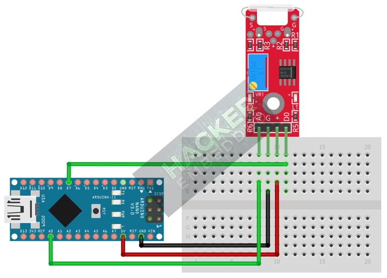
This image was created with Fritzing
Step 3 – Initialize Pin Modes
pinMode(7, INPUT); // D0 pin for digital ON/OFF detection
We will use the on-board LED (Pin 13) to reflect the digital trigger state.
4. Writing Dual-Mode Sensing Code
We will write code that simultaneously monitors both the precise analog proximity and the simple digital switch state. We’ll use the onboard LED (Pin 13) to reflect the digital state (D0).
Open main.ino and implement the following code.
const int DIGITAL_PIN = 7; // D0 Output
const int ANALOG_PIN = A0; // A0 Output
const int LED_PIN = 13; // Built-in LED
void setup() {
pinMode(LED_PIN, OUTPUT);
pinMode(DIGITAL_PIN, INPUT);
Serial.begin(9600);
Serial.println("KY-025 Dual-Mode Magnetic Sensor Ready!");
}
void loop() {
// 1. Read Digital State (D0)
// Assuming Active HIGH: HIGH when the magnet is strong enough (set by pot)
int digitalState = digitalRead(DIGITAL_PIN);
// 2. Read Analog State (A0)
// Raw 0-1023 value, often proportional to field strength
int analogValue = analogRead(ANALOG_PIN);
// Control LED based on Digital Output
if (digitalState == HIGH) {
digitalWrite(LED_PIN, LOW); // Turn LED OFF (No Magnet)
} else {
digitalWrite(LED_PIN, HIGH); // Turn LED ON (Magnet Detected)
}
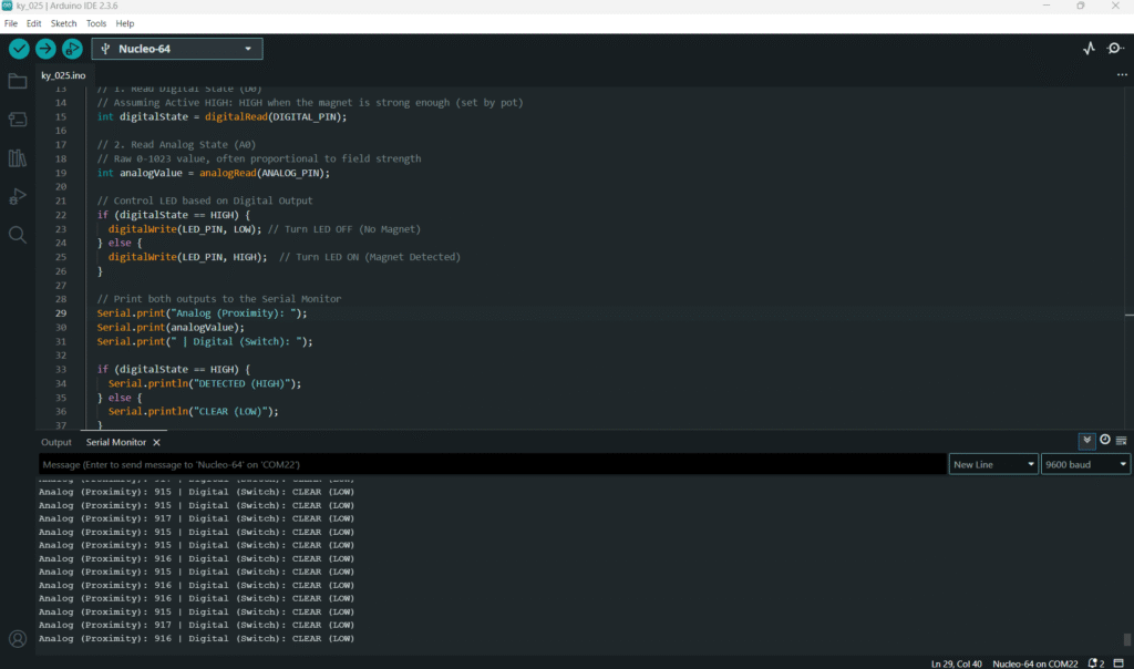
// Print both outputs to the Serial Monitor
Serial.print("Analog (Proximity): ");
Serial.print(analogValue);
Serial.print(" | Digital (Switch): ");
if (digitalState == HIGH) {
Serial.println("DETECTED (HIGH)");
} else {
Serial.println("CLEAR (LOW)");
}
delay(100);
}
Code Explanation
- D0 Output: The module’s internal circuitry (often using a comparator and the potentiometer) converts the continuous magnetic field strength into a digital HIGH or LOW signal. We read this with digitalRead().
- A0 Output: This pin provides the raw voltage from the magnetic sensing element (reed or Hall) to the Arduino, which we read with analogRead().
5. Adjusting Sensitivity (Potentiometer)
The small potentiometer on the KY-025 module controls the Digital Threshold for the D0 pin:
- Open the Serial Monitor and observe the analogValue.
- Bring a magnet to the sensor and notice the maximum and minimum analogValue you can achieve.
- Slowly turn the potentiometer. You will find that the point at which the Digital (Switch) output changes from “CLEAR (LOW)” to “DETECTED (HIGH)” moves closer or farther from the sensor.
This allows you to tune the switch distance without changing the Arduino code.
6. Uploading and Running the Project
Step 1 – Build
Click the Verify button (checkmark icon) in the Arduino IDE to compile the sketch.
Step 2 – Upload
- Connect your Arduino board via USB.
- Select the correct board and COM port.
- Click the Upload (arrow icon) button.
Step 3 – Test
- Open the Serial Monitor.
- Move a magnet closer to the sensor.
- Observe the Analog value changing continuously.
- Once the magnet is close enough (based on the potentiometer setting), the Digital state should switch to HIGH, and the onboard LED (Pin 13) should turn ON.
7. Hands-On Lab Recap
You’ve learned:
- How to simultaneously read digital and analog data from a single module.
- How to use the digital output (D0) for a simple, threshold-based switch.
- How to use the analog output (A0) for quantitative proximity data.
- The function of the onboard potentiometer for setting the digital trigger level.
This concludes your comprehensive series on fundamental KY-series modules and essential Arduino I/O skills.
8. Common Issues & Fixes
| Issue | Cause | Solution |
|---|---|---|
| Analog value is fixed at 0 or 1023. | A0 pin wired incorrectly or faulty module. | Check the A0 pin connection to Analog Pin A0. Ensure VCC and GND are secure. |
| Digital state never changes (stuck HIGH or LOW). | Potentiometer is set to its extreme limit. | Adjust the onboard potentiometer using a small screwdriver until the digital output changes when the magnet is near. |
| Digital works, but Analog does not respond to the magnet. | Faulty module or incorrect component used for A0. | The A0 output relies on a second, Hall-like circuit. Confirm the VCC and GND are correct. |

