Arduino Tutorial: KY-027 Magic Light Cup Module
Abstract
Learn how to use the KY-027 Magic Light Cup Module with Arduino. This unusual module combines a mercury-free tilt switch with a high-brightness LED. The module’s behavior (turning the LED ON/OFF) can be controlled by a combination of the tilt state and a digital signal from the Arduino. This tutorial focuses on configuring an input pin to read the tilt and an output pin to control the LED.
1. Introduction
The KY-027 module provides a simple, fun way to create interactive visual feedback. The “Magic Light Cup” effect is achieved by having a mercury-free tilt switch (similar to the KY-020) and a high-brightness LED on a single board. The module allows the Arduino to:
- Supply power to the system.
- Read the tilt state of the sensor (Digital Input).
- Control the LED state independently (Digital Output).
In this episode, you’ll learn:
- How the module integrates input and output
- How to use one Arduino pin to read the tilt status.
- How to use a second Arduino pin to control the LED.
- How to write code that makes the LED turn ON only when the cup is tilted, mimicking the effect of liquid sloshing.
This project integrates input and output for an intuitive, interactive result.
2. Prerequisites
Make sure you have:
- An Arduino Uno or compatible board.
- One KY-027 Magic Light Cup Module.
- Jumper Wires.
- Arduino IDE
3. Wiring and Setup for Arduino
The KY-027 module has four pins, two for power and two for signal I/O.
Step 1 – Identify Pins
The module typically has four pins:
- GND (Ground)
- VCC (5V Power)
- D7 (Digital Input – Tilt Sensor Signal)
- D8 (Analog Output – Often unused, will be ignored in this digital tutorial)
Step 2 – Connect the Module
Wire the module to the Arduino as follows. We will use the D0 pin to read the tilt state. The LED is usually powered directly by the VCC pin on the module, and its control is integrated into the D0 pin on some versions, but we will use the Arduino to act as the power switch for the whole module via the VCC pin for simple ON/OFF control.
Alternative Wiring (Direct Control): Some versions of the KY-027 allow the Arduino to act as the power supply. For simplicity and reliability of the “Magic Light Cup” effect, we will wire the module to constantly be “listening,” and let the D0 pin report the tilt status, which we then use to control a different output (e.g., Arduino’s Pin 13 LED).
Wiring for Reading Tilt State (D0):
- Connect the GND pin of the KY-027 to the GND pin on the Arduino.
- Connect the VCC pin of the KY-027 to the 5V pin on the Arduino (Keeps module powered).
- Connect the D0 pin of the KY-027 to Arduino Digital Pin 7 (Input).
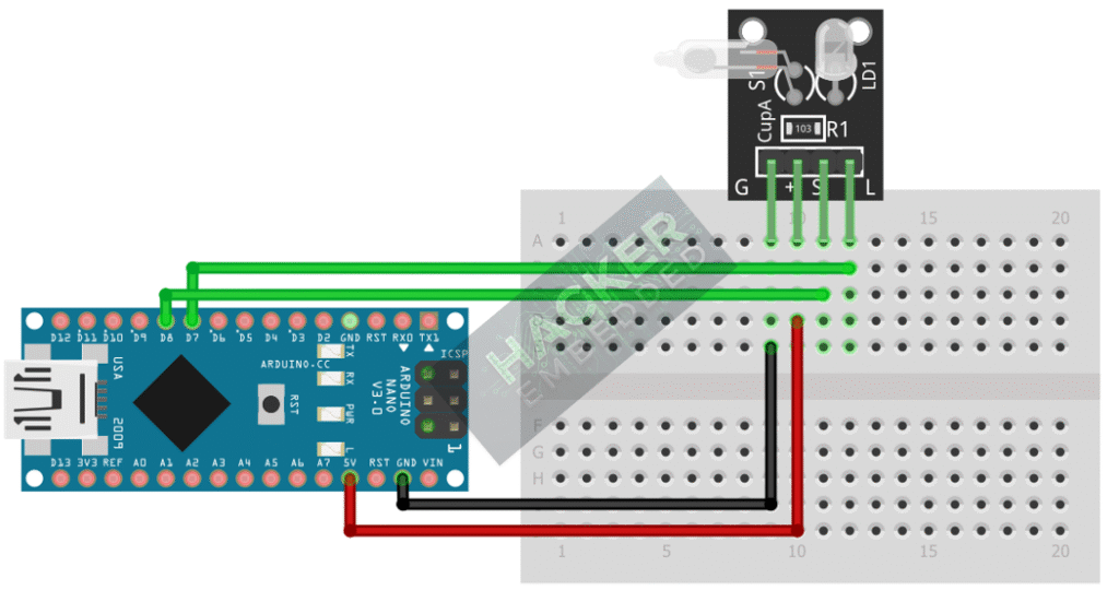
This image was created with Fritzing
Step 3 – Initialize Pin Modes
pinMode(7, INPUT); // D0 pin for digital ON/OFF detection
We will use the on-board LED (Pin 13) to reflect the digital trigger state.
4. Writing Interactive Control Code
Open main.ino and implement the following code. This program will turn the Arduino’s built-in LED (Pin 13) ON only when the module is tilted.
					const int TILT_SENSOR_PIN = 7;
const int LED_PIN = 13; // Built-in LED

void setup() {
  pinMode(LED_PIN, OUTPUT);
  // D0 pin from the module (tilt switch) is an Input
  pinMode(TILT_SENSOR_PIN, INPUT);

  Serial.begin(9600);
  Serial.println("KY-027 Magic Light Cup Test Ready!");
}

void loop() {
  // Read sensor state (HIGH/LOW based on tilt)
  // The D0 pin will be HIGH when the switch is open (not tilted) and LOW when closed (tilted).
  int tiltState = digitalRead(TILT_SENSOR_PIN);

  if(tiltState == LOW) // Check if tilted (Active LOW state)
  {
    digitalWrite(LED_PIN, HIGH); // Turn Arduino LED ON
    Serial.println("Status: TILTED! Light ON.");
  }
  else
  {
    digitalWrite(LED_PIN, LOW); // Turn Arduino LED OFF
    Serial.println("Status: Level. Light OFF.");
  }

  delay(50);
}
Code Explanation
- D0 Behavior: Like many module switches, the D0 pin outputs an Active LOW signal when the tilt switch closes its contacts (e.g., when the “cup” is tipped over).
- Interactive Control: The Arduino reads this low signal and immediately acts upon it, switching its own output LED HIGH. This demonstrates using the tilt sensor as a digital input to control any other component.
5. Uploading and Running the Project
Step 1 – Build
Click the Verify button (checkmark icon) in the Arduino IDE to compile the sketch.
Step 2 – Upload
- Connect your Arduino board via USB.
- Select the correct board and COM port.
- Click the Upload (arrow icon) button.
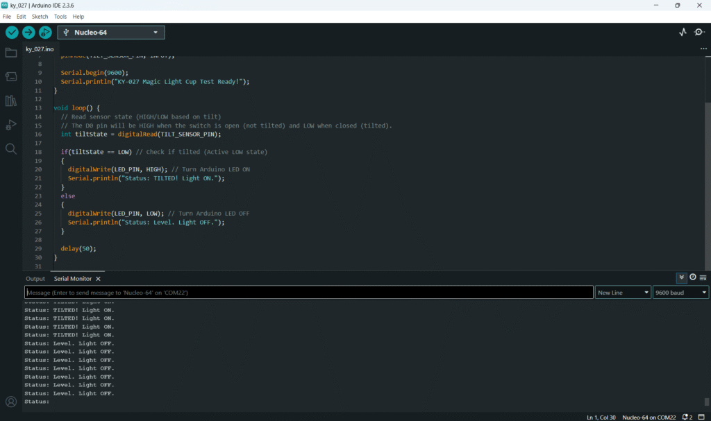
Step 3 – Test
- Open the Serial Monitor (Tools > Serial Monitor).
- Keep the module level: the Arduino LED (Pin 13) should be OFF.
- Tilt the KY-027 module past its activation angle: the Arduino LED should turn ON, and the monitor should show “Status: TILTED! Light ON.”
- Return the module to its level position: the LED should turn OFF.
6. Hands-On Lab Recap
You’ve learned:
- How the KY-027 combines an input (tilt switch on D7) and output (onboard LED).
- How to wire the D0 pin as a Digital Input to read the tilt state.
- How to use the input signal to create an interactive output response on another Arduino pin.
This completes your foundation in basic digital input and output sensors.
7. Common Issues & Fixes
| Issue | Cause | Solution |
|---|---|---|
| LED is always ON when module is level. | Logic Inversion required. | Try reversing the logic condition: change LOW to HIGH in the if statement. |
| The onboard KY-027 LED never lights up. | The onboard LED's control signal is often independent of the D0 pin, or it's controlled by the A0 pin which isn't used. | Focus on controlling the Arduino's LED (Pin 13) to confirm the sensor is working. The KY-027's own LED often works best when the module is simply powered and the tilt switch completes its own internal circuit. |
| The sensor reading is unreliable. | Poor power/ground connection or excessive motion. | Ensure the VCC and GND connections are secure. Introduce a small delay(50); to stabilize the reading. |

