
Arduino Tutorial: KY-029 Dual Color LED Module
Abstract
Learn how to use the KY-029 Dual Color LED Module with Arduino. This module contains a single component that can display two distinct colors (typically Red and Green) and, when both are mixed via Pulse Width Modulation (PWM), a third color (Yellow/Amber) can be achieved. This tutorial focuses on using digital output for ON/OFF control and PWM for brightness and color mixing.
1. Introduction
The KY-029 module is essentially two separate LEDs (Red and Green) in a single package, usually wired in a Common Cathode configuration. By controlling the voltage supplied to each color independently, you can: 1) turn on Red, 2) turn on Green, or 3) turn both on to produce a mixed color.
In this episode, you’ll learn:
- The Common Cathode configuration of the KY-029.
- How to use digitalWrite() to display pure Red and pure Green.
- How to use analogWrite() (PWM) to achieve color mixing (Yellow/Amber).
- A technique for creating a smooth color transition between the two primary colors.
This project offers an efficient way to provide multi-state visual feedback (e.g., Red=Stop, Green=Go, Yellow=Warning).
2. Prerequisites
Make sure you have:
- An Arduino Uno or compatible board.
- One KY-029 Dual Color LED Module.
- Jumper Wires.
- Arduino IDE
3. Wiring and Setup for Arduino
The KY-029 is a Common Cathode module, meaning the common ground pin must be connected to GND, and the individual color pins are activated by a HIGH signal (or PWM).
Step 1 – Identify Pins
The module typically has three pins: R (Red Anode), G (Green Anode), and Ground (GND).
Step 2 – Connect the Module
Wire the module to the Arduino. We will connect the color pins to PWM pins to allow for mixing and dimming.
KY-029 Pin | Function | Arduino Connection |
G (Green Anode) | Green LED | Digital Pin ~11 (PWM) |
R (Red Anode) | Red LED | Digital Pin ~10 (PWM) |
– / GND | Common Cathode | GND Pin |
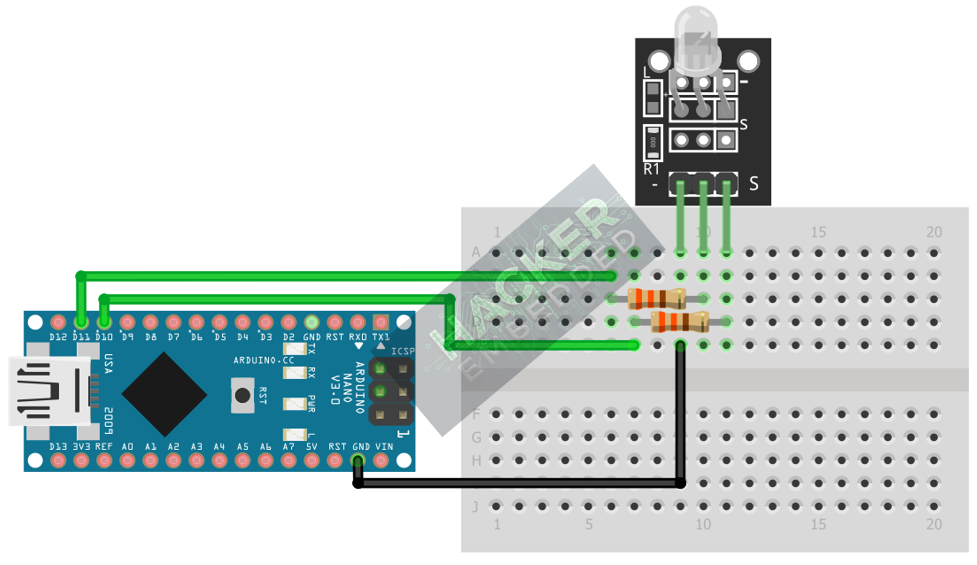
This image was created with Fritzing
Note: The KY-029 usually includes built-in current-limiting resistors, so external resistors are typically not needed. In case they are not mounted, consider adding 330ohm resistors, as shown in the circuit diagram.
Step 3 – Initialize Pin Mode
Both color pins must be initialized as OUTPUT in the setup() function:
pinMode(RED_PIN, OUTPUT);
pinMode(GREEN_PIN, OUTPUT);
4. Writing Color Control Code
Open main.ino and implement the following code. This code demonstrates the three primary states: Red, Green, and the mixed Yellow/Amber color.
					const int RED_PIN = 10;
const int GREEN_PIN = 11;

// Helper function to turn off all colors
void allOff() {
  digitalWrite(RED_PIN, LOW);
  digitalWrite(GREEN_PIN, LOW);
}

void setup() {
  pinMode(RED_PIN, OUTPUT);
  pinMode(GREEN_PIN, OUTPUT);
  Serial.begin(9600);
}

void loop() {
  // 1. Display RED (Using simple Digital HIGH/LOW)
  allOff(); // Start clean
  digitalWrite(RED_PIN, HIGH);
  Serial.println("Displaying RED");
  delay(1500);

  // 2. Display GREEN
  allOff();
  digitalWrite(GREEN_PIN, HIGH);
  Serial.println("Displaying GREEN");
  delay(1500);

  // 3. Display YELLOW/AMBER (Using PWM/analogWrite for mixing)
  // Max brightness for both colors creates the mixed third color
  analogWrite(RED_PIN, 255);
  analogWrite(GREEN_PIN, 255);
  Serial.println("Displaying YELLOW/AMBER");
  delay(1500);
}
Code Explanation
- Pure Colors: Achieved by setting one pin HIGH (digitalWrite()) and the other LOW.
- Mixed Color (Yellow/Amber): Achieved by setting both pins to a high PWM value (e.g., 255 using analogWrite()). Since the colors are emitted simultaneously, the human eye perceives the combined color.
5. Creating a Fading Transition
To achieve a smooth transition between Red and Green (passing through a spectrum of Yellow/Amber), we need to use a single loop that fades one color out while fading the other color in.
					void fadeRedToGreen() {
  int redValue = 255;
  int greenValue = 0;

  // Transition from RED (255, 0) to GREEN (0, 255)
  // Red fades out (255 -> 0), Green fades in (0 -> 255)
  for (int i = 0; i <= 255; i += 5) {
    // Red brightness = 255 - i (starts high, ends low)
    analogWrite(RED_PIN, 255 - i);

    // Green brightness = i (starts low, ends high)
    analogWrite(GREEN_PIN, i);

    delay(20); // Control the speed of the fade
  }
}
Note: Comment the function call fadeRedToGreen() inside the loop() to test the transition.
6. Uploading and Running the Project
Step 1 – Build
Click the Verify button (checkmark icon) in the Arduino IDE to compile the sketch.
Step 2 – Upload
- Connect your Arduino board via USB.
- Select the correct board and COM port.
- Click the Upload (arrow icon) button.
Step 3 – Test
- If you ran the code from Section 4, the LED should cycle sharply through Red, Green, and Yellow/Amber.
- If you ran the fadeRedToGreen() function, the LED should smoothly transition from Red through Yellow/Amber to Green, demonstrating successful PWM-based color mixing.
7. Hands-On Lab Recap
You’ve learned:
- How to identify and wire a Common Cathode Dual Color LED.
- How to use digitalWrite() for pure colors.
- How to use analogWrite() (PWM) to create a mixed third color.
- The technique of cross-fading to create smooth color transitions.
This adds advanced visual indication capability to your projects.
8. Common Issues & Fixes
| Issue | Cause | Solution |
|---|---|---|
| Only one color works, or no color works. | Wiring error, especially on the Common Cathode (GND) pin. | Ensure the - / GND pin is securely connected to the Arduino's GND pin. |
| The LED only displays ON/OFF states, no mixed color. | Using digitalWrite() for the mixed state. | Ensure you use analogWrite() with a value greater than 0 on both pins simultaneously to achieve color mixing. |
| Mixed color is dim or weak. | Low PWM values used for mixing. | Use the maximum value, 255, for both colors (e.g., analogWrite(PIN, 255);) to create the brightest mixed color. |

