Arduino Tutorial: KY-031 Knock Sensor Module
Abstract
Learn how to configure Arduino digital input pins to interface with the KY-031 Knock Sensor Module. This step-by-step tutorial covers wiring the module to detect physical impacts and controlling the on-board LED based on the detected vibration signal.
1. Introduction
Following previous episodes on digital output, we now tackle digital input from a switch-like sensor. The KY-031 module uses a spring-based switch to momentarily close a circuit when it receives a shock or vibration. This allows your board to react to physical contact.
In this episode, you’ll learn:
- How to configure Arduino pins as digital input.
- How the KY-031 knock detection principle
- How to read the sensor signal using digitalRead().
- Simple techniques for handling sensor bouncing (chatter).
This project will make your board respond to physical interaction, opening the door to security systems or interactive musical devices.
2. Prerequisites
Make sure you have:
- An Arduino Uno or compatible board.
- One KY-031 Knock Sensor Module.
- Jumper Wires.
- Arduino IDE
3. Wiring and Setup for Arduino
The KY-031 module requires 5V power and outputs a single digital signal.
Step 1 – Identify Pins
The module has three pins: Signal (S or OUT), VCC (+), and Ground (- or GND).
Step 2 – Connect the Module
Wire the module to the Arduino as follows:
- Connect the – / GND pin of the KY-031 to the GND pin on the Arduino.
- Connect the + / VCC pin of the KY-031 to the 5V pin on the Arduino.
- Connect the S / Signal pin of the KY-031 to Arduino Digital Pin 8.
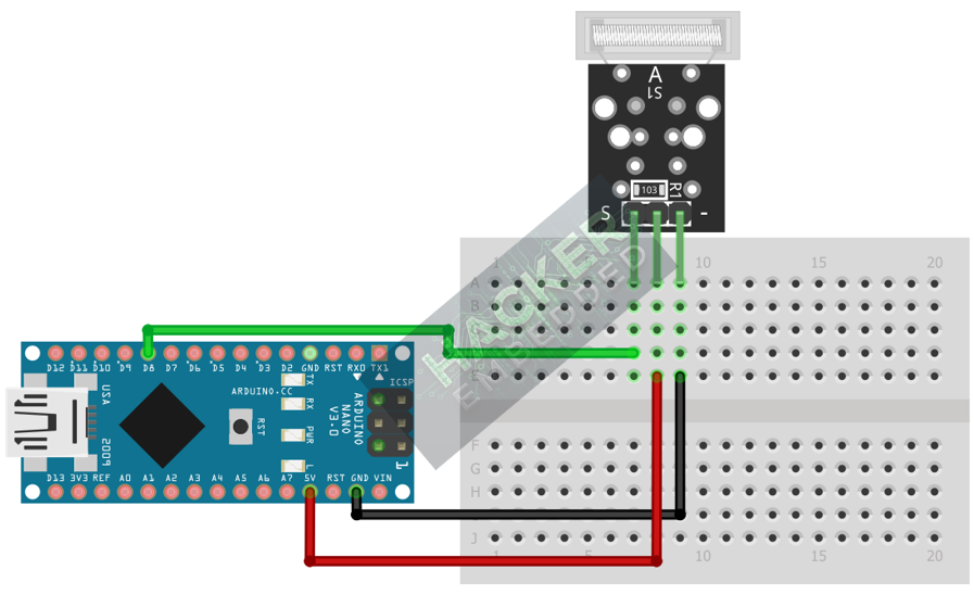
This image was created with Fritzing
Step 3 – Initialize Pin Mode
In the setup() function of your code, you must initialize the signal pin as an input:
pinMode(8, INPUT);
We will use the on-board LED (Pin 13) as our output indicator, which must be set to OUTPUT.
4. Writing Knock Detection Code
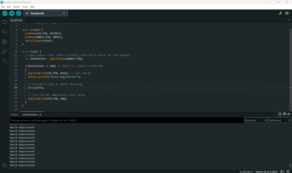
Open main.ino and implement the following code. This code will flash the built-in LED (Pin 13) when a knock is registered on Pin 8.
					const int KNOCK_PIN = 8;
const int LED_PIN = 13; // Built-in LED

void setup() {
  pinMode(LED_PIN, OUTPUT);
  pinMode(KNOCK_PIN, INPUT);
  Serial.begin(9600);
}

void loop() {
  // Read sensor state (HIGH is usually detected on knock for this module)
  int knockState = digitalRead(KNOCK_PIN);

  if(knockState == LOW) // Check if a knock is detected
  {
    digitalWrite(LED_PIN, HIGH); // Turn LED ON
    Serial.println("Knock Registered!");

    // Proceed to Step 5: Handle Bouncing
    delay(200);

    // Turn LED OFF immediately after delay
    digitalWrite(LED_PIN, LOW);
  }
}
Code Explanation
- digitalRead(KNOCK_PIN) returns the sensor’s current voltage state (HIGH or LOW).
- The if statement checks for the LOW signal indicating a knock.
- digitalWrite(LED_PIN, HIGH) illuminates the LED briefly as an alert.
5. Handling Sensor Bouncing
Like any mechanical switch, the internal spring of the KY-031 can bounce against the contact when struck, causing the signal to flicker multiple times (HIGH-LOW-HIGH) for a single physical knock.
Simple Debounce Method
To prevent the Arduino from registering these multiple pulses, we introduce a short time delay after the first detected pulse.
Tip: A 200ms delay is generally effective for debouncing this type of mechanical sensor without making the response feel too sluggish.
6. Uploading and Running the Project
Step 1 – Build
Click the Verify (checkmark icon) button in the Arduino IDE to compile the sketch.
Step 2 – Upload
- Connect your Arduino board via USB.
- Select the correct board and COM port.
- Click the Upload (arrow icon) button.
Step 3 – Test
- Open the Serial Monitor (Tools > Serial Monitor).
- Tap the KY-031 module or the surface it’s resting on.
- The on-board LED should flash briefly, and “Knock Registered!” should appear once in the Serial Monitor for each single tap.
7. Hands-On Lab Recap
You’ve learned:
- How to configure Digital pins as input using pinMode().
- How to read the KY-031 sensor state with digitalRead().
- How to control an LED based on a physical shock event.
- A basic technique for handling sensor bouncing using a delay.
This adds physical interactivity to your Arduino projects, preparing you for interrupts and more complex input handling in the next tutorials.
8. Common Issues & Fixes
| Issue | Cause | Solution |
|---|---|---|
| LED never responds to knocks. | Incorrect power wiring (VCC/GND reversed). | Double-check that 5V is connected to the + pin and GND to the - pin. |
| LED is always ON or flashing rapidly. | Incorrect logic or excessive bouncing. | Try reversing the logic condition: change if (knockState == HIGH) to if (knockState == LOW). Increase the delay() value. |
| Code compiles but sensor doesn't work. | Signal pin misconfiguration. | Ensure pinMode(KNOCK_PIN, INPUT); is called and the KNOCK_PIN matches the wire on the Arduino. |

