Arduino Tutorial: KY-032 Infrared Obstacle Avoidance Sensor Module
Abstract
Learn how to use the KY-032 Infrared Obstacle Avoidance Sensor Module with Arduino. This module is a crucial component in robotics for non-contact object detection and provides a clean digital ON/OFF signal. This tutorial focuses on configuring a digital input pin to read the obstacle state and using the module’s onboard potentiometer to tune the detection distance.
1. Introduction
The KY-032 module operates similarly to the photo interrupter (KY-010) but detects objects via reflection rather than interruption. It integrates:
- IR Emitter: An LED that constantly sends out an invisible infrared beam.
- IR Receiver: A phototransistor that detects the reflected IR light bouncing off an object.
- Comparator Circuitry: Converts the analog reflection intensity into a sharp digital HIGH or LOW signal.
- Potentiometer: Allows the user to adjust the trigger threshold, effectively setting the detection distance (range).
In this episode, you’ll learn:
- The principle of IR reflection sensing.
- How to use the module’s digital output (D0) for reliable object detection.
- How to use the onboard potentiometer to set the sensing range.
- How to implement a simple obstacle avoidance routine.
This project provides a cost-effective and flexible way to add proximity sensing to mobile platforms.
2. Prerequisites
Make sure you have:
- An Arduino Uno or compatible board.
- One KY-032 Infrared Obstacle Avoidance Sensor Module.
- One object for detection (e.g., your hand or a box).
- Jumper Wires.
- Arduino IDE
3. Wiring and Setup for Arduino
The KY-032 module is a digital output device, but some versions may also include an analog output (A0) which we will ignore for this basic digital tutorial.
Step 1 – Identify Pins
The module typically has three pins: OUT (Signal/D0), VCC (+), and GND (− or GND).
Step 2 – Connect the Module
Wire the module to the Arduino as follows. When an object is detected, the reflected light often causes the signal pin to go LOW (Active LOW logic), and HIGH when the path is clear.
- Connect the GND pin of the KY-032 to the GND pin on the Arduino.
- Connect the VCC pin of the KY-032 to the 5V pin on the Arduino.
- Connect the OUT/D0 pin of the KY-032 to Arduino Digital Pin 7.
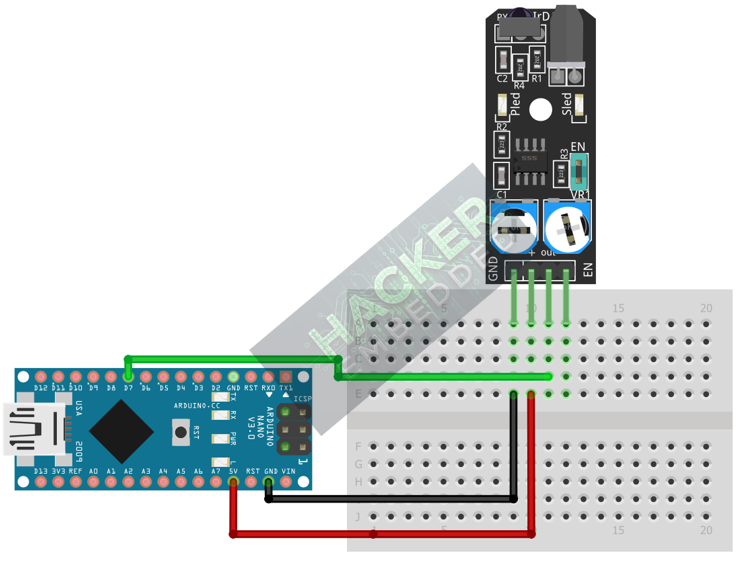
This image was created with Fritzing
Step 3 – Initialize Pin Mode
In the setup() function of your code, set the signal pin as a standard input:
pinMode(7, INPUT);
We will use the on-board LED (Pin 13) as our output indicator.
4. Writing Obstacle Detection Code
We will write simple code that checks the digital output of the sensor and turns the built-in LED (Pin 13) ON when an obstacle is detected.
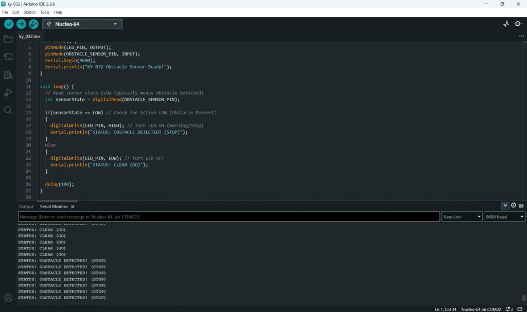
Open main.ino and implement the following code.
					const int OBSTACLE_SENSOR_PIN = 7;
const int LED_PIN = 13; // Built-in LED

void setup() {
  pinMode(LED_PIN, OUTPUT);
  pinMode(OBSTACLE_SENSOR_PIN, INPUT);
  Serial.begin(9600);
  Serial.println("KY-032 Obstacle Sensor Ready!");
}

void loop() {
  // Read sensor state (LOW typically means obstacle detected)
  int sensorState = digitalRead(OBSTACLE_SENSOR_PIN);

  if(sensorState == LOW) // Check for Active LOW (Obstacle Present)
  {
    digitalWrite(LED_PIN, HIGH); // Turn LED ON (Warning/Stop)
    Serial.println("STATUS: OBSTACLE DETECTED! (STOP)");
  }
  else
  {
    digitalWrite(LED_PIN, LOW); // Turn LED OFF
    Serial.println("STATUS: CLEAR (GO)");
  }

  delay(100);
}
Code Explanation
- Reflection Principle: The reflection intensity dictates the sensor’s output. A nearby obstacle causes high reflection, triggering the comparator.
- Active LOW: The comparator on the module is usually configured to output LOW when the reflection intensity crosses the threshold set by the potentiometer.
5. Calibrating the Detection Range
The key to this module is the onboard potentiometer (trimpot). It controls the sensitivity of the receiver, which directly translates to the detection distance.
Procedure:
- Upload the code from Section 4.
- Open the Serial Monitor.
- Place an obstacle (e.g., a hand) approximately 5cm away from the sensor face.
- Slowly turn the potentiometer with a small screwdriver. You will find a point where the Serial Monitor output flips from “CLEAR (GO)” to “OBSTACLE DETECTED! (STOP)”.
- Test the distance: If you move the obstacle slightly farther than 5cm, the output should flip back to “CLEAR”. If it doesn’t, you need to adjust the potentiometer again until the switch point is precisely 5cm.
6. Uploading and Running the Project
Step 1 – Build & Upload
Complete the standard build and upload process.
Step 2 – Test
- Calibrate the sensor using the procedure in Section 5 to a distance of your choosing.
- Observe the built-in LED: it should turn ON immediately when an object is placed within the calibrated distance and turn OFF when the object is removed.
7. Hands-On Lab Recap
You’ve learned:
- The principle of IR reflective proximity sensing.
- How to use the digital output (D0) for reliable, non-contact switching.
- The crucial skill of calibrating the detection range using the onboard potentiometer.
This concludes the comprehensive series on fundamental KY-series modules, providing you with a complete toolkit for basic electronic projects.
8. Common Issues & Fixes
| Issue | Cause | Solution |
|---|---|---|
| LED is always ON or never turns ON. | Potentiometer is set incorrectly. | Calibrate the sensor (Section 5). The pot may be set to detect objects infinitely far away (always LOW) or only objects immediately touching the sensor (always HIGH). |
| Sensor triggers on distant objects (e.g., walls). | Detection range is too high. | Turn the potentiometer counter-clockwise to reduce sensitivity and decrease the range. |
| Sensor triggers intermittently. | Ambient light interference (sunlight or bright lamps). | Shield the sensor from direct, strong light sources. The IR receiver can be saturated by external IR. |
| Sensor output is always the opposite of expected. | Active HIGH/LOW assumption is reversed. | Change the if statement logic from if(sensorState == LOW) to if(sensorState == HIGH) and retest. |

