Arduino Tutorial: KY-033 Line Tracking Sensor Module
Abstract
Learn how to use the KY-033 Line Tracking Sensor Module with Arduino. This sensor is crucial for line-following robots, using an infrared light source and a phototransistor to detect differences in light reflection between light (white) and dark (black) surfaces. This tutorial focuses on configuring a digital input pin to read the sensor’s ON/OFF state and calibrating its sensitivity using the onboard potentiometer.
1. Introduction
The KY-033 is a specialized version of a reflective IR sensor (like the KY-032) designed specifically for detecting lines. It measures the intensity of reflected light: dark surfaces (like a black line) absorb most of the IR light, while light surfaces (like a white floor) reflect most of it. The module integrates:
- IR Emitter/Receiver Pair: Shines and detects the reflected IR light.
- Comparator Circuitry: Converts the reflection intensity into a sharp digital HIGH or LOW signal.
- Potentiometer: Allows tuning the trigger threshold, crucial for distinguishing a line from a floor.
In this episode, you’ll learn:
- The principle of reflectance sensing for line detection.
- How to use the module’s digital output (D0) for simple line detection.
- How to use the onboard potentiometer to accurately calibrate the sensor for a specific line/floor combination.
This project is the fundamental building block for any line-following robot.
2. Prerequisites
Make sure you have:
- An Arduino Uno or compatible board.
- One KY-033 Line Tracking Sensor Module.
- A white surface with a thick black line drawn on it for testing.
- Jumper Wires.
- Arduino IDE
3. Wiring and Setup for Arduino
The KY-033 module is a digital output device.
Step 1 – Identify Pins
The module typically has three pins: OUT (Signal/D0), VCC (+), and GND (− or GND).
Step 2 – Connect the Module
Wire the module to the Arduino as follows. The common convention is:
- HIGH output when the sensor is over the light surface (high reflection).
- LOW output when the sensor is over the dark surface (low reflection).
- Note: This behavior can be reversed based on the potentiometer setting.
- Connect the GND pin of the KY-033 to the GND pin on the Arduino.
- Connect the VCC pin of the KY-033 to the 5V pin on the Arduino.
- Connect the OUT/D0 pin of the KY-033 to Arduino Digital Pin 7.
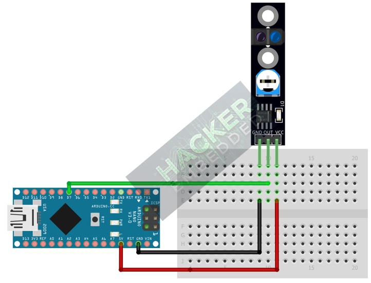
This image was created with Fritzing
Step 3 – Initialize Pin Mode
In the setup() function of your code, set the signal pin as a standard input:
pinMode(7, INPUT);
We will use the on-board LED (Pin 13) as our output indicator.
4. Writing Line Detection Code
We will write simple code that checks the digital output of the sensor and turns the built-in LED (Pin 13) ON when it detects the black line.
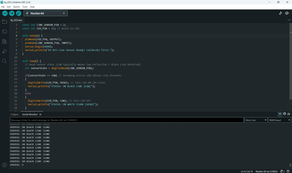
Open main.ino and implement the following code.
					const int LINE_SENSOR_PIN = 7;
const int LED_PIN = 13; // Built-in LED

void setup() {
  pinMode(LED_PIN, OUTPUT);
  pinMode(LINE_SENSOR_PIN, INPUT);
  Serial.begin(9600);
  Serial.println("KY-033 Line Sensor Ready! Calibrate first.");
}

void loop() {
  // Read sensor state (LOW typically means low reflection / Black Line Detected)
  int sensorState = digitalRead(LINE_SENSOR_PIN);

  if(sensorState == LOW) // Assuming Active LOW (Black Line Present)
  {
    digitalWrite(LED_PIN, HIGH); // Turn LED ON (On Line)
    Serial.println("STATUS: ON BLACK LINE (LOW)");
  }
  else
  {
    digitalWrite(LED_PIN, LOW); // Turn LED OFF
    Serial.println("STATUS: ON WHITE FLOOR (HIGH)");
  }

  delay(50);
}
Code Explanation
- Reflection Difference: The low reflection from the black line causes the phototransistor to receive less signal, which typically triggers the comparator to output LOW.
- Digital Signal: The Arduino reads this clean LOW signal to determine if the line is under the sensor.
5. Calibrating the Sensor (Crucial Step)
The potentiometer must be tuned to perfectly distinguish between your specific line color and floor color.
Procedure:
- Upload the code from Section 4.
- Open the Serial Monitor.
- Place the sensor directly over the white floor.
- Place the sensor directly over the black line.
- Observe the D0 LED on the module and the Serial Monitor output. If the sensor is over the line, the module’s onboard LED should turn ON, and the Serial Monitor should show LOW.
- Adjust the Potentiometer: Slowly turn the trimpot until the module’s onboard LED flips its state exactly when moving the sensor across the boundary between the white and black surfaces.
- Final Test: The sensor should consistently output one state (e.g., HIGH) over white and the other state (LOW) over black. If it works, your calibration is complete.
6. Uploading and Running the Project
Step 1 – Build & Upload
Complete the standard build and upload process.
Step 2 – Test
- Calibrate the sensor using the procedure in Section 5.
- Move the sensor over the white surface: the Arduino LED (Pin 13) should be OFF.
- Move the sensor over the black line: the Arduino LED (Pin 13) should turn ON.
7. Hands-On Lab Recap
You’ve learned:
- The principle of reflectance difference for line detection.
- The critical role of the potentiometer in setting the discrimination threshold.
- How to use the digital output (D0) for two-state environment sensing.
This concludes the comprehensive series on fundamental KY-series modules, providing you with a complete toolkit for basic electronic projects.
8. Common Issues & Fixes
| Issue | Cause | Solution |
|---|---|---|
| Sensor doesn't work reliably on one color. | Potentiometer is misaligned. | Recalibrate the sensor carefully (Section 5). The threshold is too close to one color's reading. |
| Sensor triggers on distant objects (shadows, edges). | Poor lighting conditions or sensor too high off the ground. | Ensure the sensor is close to the surface (2-10mm). Use consistent overhead lighting. |
| Sensor works, but output logic is reversed (HIGH on black, LOW on white). | Logic configuration is reversed. | Change the if statement logic to if(sensorState == HIGH) to control the Arduino LED. The module itself can only be fixed by tuning the potentiometer. |
| Sensor is slow to respond. | Excessive delay in code. | The 50ms delay is fine for human testing; remove it entirely for robot motion control. |

