Arduino Tutorial: KY-035 Analog Hall Magnetic Sensor Module
Abstract
Learn how to use the KY-035 Analog Hall Magnetic Sensor Module with Arduino. Unlike the digital KY-003, this sensor outputs a variable analog voltage proportional to the magnetic field strength. This tutorial focuses on configuring an Analog Pin to read the magnetic field’s intensity and polarity using analogRead().
1. Introduction
The KY-035 utilizes a linear Hall Effect sensor (often the 49E or similar) that produces a continuous voltage output.
- No Magnet: The output voltage is centered near VCC/2 (half the supply voltage, e.g., 2.5V or ≈512 raw ADC).
- Magnet Present: The voltage moves up or down from the center point, depending on the polarity (North or South pole) and the strength of the magnet.
In this episode, you’ll learn:
- The concept of a ratiometric linear Hall sensor.
- How to connect the signal to an Analog Input Pin.
- How to read and interpret the raw ADC value (0-1023).
- How to differentiate between the North and South poles of a magnet.
This project introduces a method for quantitative measurement of magnetic fields, ideal for precise positioning and speed control.
2. Prerequisites
Make sure you have:
- An Arduino Uno or compatible board.
- One KY-035 Analog Hall Magnetic Sensor Module.
- One small magnet (e.g., neodymium magnet).
- Jumper Wires.
- Arduino IDE
3. Wiring and Setup for Arduino
The KY-035 module has three pins and requires an analog input pin.
Step 1 – Identify Pins
The module has three pins: Signal (S or OUT), VCC (+), and Ground (− or GND).
Step 2 – Connect the Module
Wire the module to the Arduino as follows. The signal pin must be connected to one of the Analog Input Pins (A0-A5).
- Connect the – / GND pin of the KY-035 to the GND pin on the Arduino.
- Connect the + / VCC pin of the KY-035 to the 5V pin on the Arduino.
- Connect the S / Signal pin of the KY-035 to Arduino Analog Pin A0.
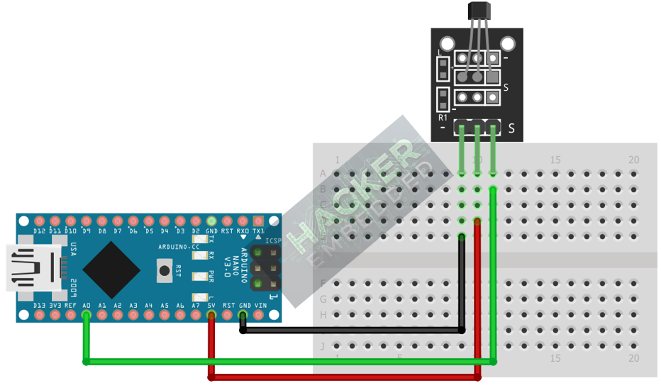
This image was created with Fritzing
Step 3 – Understanding Output Logic
When the magnetic field strength changes, the voltage changes continuously. We will read this voltage as a raw 0-1023 integer:
Raw ADC Value | Approximate Voltage | Magnetic Field |
≈512 | ≈2.5V | No Field (Ambient Noise) |
<512 (e.g., 200) | <2.5V | South Pole (or one specific pole) |
>512 (e.g., 800) | >2.5V | North Pole (or the opposite pole) |
4. Writing Analog Sensing Code
Open main.ino and implement the following code. This program reads the sensor, determines the baseline (ambient reading), and continuously reports the field strength and direction.
					const int HALL_PIN = A0;
const int CENTER_THRESHOLD = 512; // Baseline value for 2.5V (VCC/2)

void setup() {
  Serial.begin(9600);
  Serial.println("KY-035 Analog Hall Sensor Test Ready!");
  Serial.println("Reading Baseline...");
  delay(1000);
}

void loop() {
  // 1. Read Raw ADC Value (0-1023)
  int rawValue = analogRead(HALL_PIN);

  // 2. Calculate Deviation (Signed magnitude from the center point)
  int deviation = rawValue - CENTER_THRESHOLD;

  // 3. Determine Polarity and Print Output
  Serial.print("Raw: ");
  Serial.print(rawValue);
  Serial.print(" | Deviation: ");
  Serial.print(deviation);
  Serial.print(" | Field Status: ");

  if (abs(deviation) < 10) { // Check if reading is close to the baseline
    Serial.println("Ambient / No Magnet");
  } else if (deviation > 0) {
    Serial.print("STRONG (");
    Serial.print(abs(deviation));
    Serial.println(") - Pole A (e.g., North)");
  } else { // deviation < 0
    Serial.print("STRONG (");
    Serial.print(abs(deviation));
    Serial.println(") - Pole B (e.g., South)");
  }

  delay(100); // Wait for next reading
}
Code Explanation
- CENTER_THRESHOLD: We assume the baseline reading is 512 (half of 1023). If your Arduino’s 5V supply is slightly off, you might need to find the true baseline by reading rawValue when no magnet is present.
- deviation: Calculating rawValue – 512 gives a signed value. A positive deviation means the voltage increased (one pole), and a negative deviation means the voltage decreased (the other pole). The magnitude (abs(deviation)) is the field strength.
5. Uploading and Running the Project
Step 1 – Build
Click the Verify (checkmark icon) button in the Arduino IDE to compile the sketch.
Step 2 – Upload
- Connect your Arduino board via USB.
- Select the correct board and COM port.
- Click the Upload (arrow icon) button.
Step 3 – Test
- Open the Serial Monitor (Tools > Serial Monitor).
- Observe the ambient reading (should be near 512).
- Bring the magnet close to the sensor face with one side. The rawValue should jump (e.g., to 800 or higher). This is Pole A.
- Flip the magnet and bring the other side close. The rawValue should drop below the threshold (e.g., to 200 or lower). This is Pole B.
- Moving the magnet closer to the sensor will increase the deviation (stronger reading).
6. Hands-On Lab Recap
You’ve learned:
- The difference between Analog (KY-035) and Digital (KY-003) Hall sensors.
- How to read a linear voltage output using analogRead().
- How to use the VCC/2 baseline (512) to determine the polarity and strength of a magnetic field.
- A robust method for continuous magnetic field monitoring.
This is the second example of using Analog Input to convert physical phenomena into measurable data.
7. Common Issues & Fixes
| Issue | Cause | Solution |
|---|---|---|
| Reading is fixed near 1023 or 0. | Sensor not connected to a 5V supply or signal pin wrong. | Ensure VCC is 5V and the signal pin is connected to an Analog Pin (A0-A5). |
| Reading is fixed at 512, never moves. | Magnet too far away or too weak. | Use a stronger magnet (neodymium is best) and place it within a few millimeters of the sensor face. |
| Ambient reading is not 512. | 5V reference is inaccurate. | Run the code with no magnet and note the stable rawValue. Use this new value to replace the CENTER_THRESHOLD constant. |

