
Arduino Tutorial: KY-037 High Sensitivity Sound Detection Module
Abstract
Learn how to use the KY-037 High Sensitivity Sound Detection Module with Arduino. This module, an enhanced version of the KY-038, is designed to detect fainter sounds. It provides both a digital ON/OFF signal (D0) for noise events and a raw analog value (A0) representing sound intensity. This tutorial focuses on using both inputs to detect and analyze ambient sound, and calibrating the digital trigger using the onboard potentiometer.
1. Introduction
The KY-037 utilizes an amplified microphone circuit specifically optimized for higher sensitivity, allowing it to pick up quieter ambient sounds compared to standard modules. Its dual output structure makes it highly versatile:
- Analog Output (A0): Provides the amplified audio signal waveform. This value is continuous and directly correlates with the instantaneous volume of the sound captured.
- Digital Output (D0): A comparator circuit converts the amplified signal into a sharp digital HIGH or LOW signal. The trigger point for this switch is set by the potentiometer.
In this episode, you’ll learn:
- The benefit of using a high-sensitivity microphone.
- How to use the analog output (A0) to measure instantaneous sound volume.
- How to use the digital output (D0) for reliable, threshold-based noise detection.
- How to use the module’s onboard potentiometer to set the digital trigger sensitivity.
This project enables precise audio-based automation.
2. Prerequisites
Make sure you have:
- An Arduino Uno or compatible board.
- One KY-037 High Sensitivity Sound Detection Module.
- Jumper Wires.
- Arduino IDE
3. Wiring and Setup for Arduino
The KY-037 module has four pins and requires both digital and analog input pins.
Step 1 – Identify Pins
The module typically has four pins: A0 (Analog Output), D0 (Digital Output), VCC (+), and GND (− or GND).
Step 2 – Connect the Module
Wire the module to the Arduino as follows:
- Connect the GND pin of the KY-037 to the GND pin on the Arduino.
- Connect the VCC pin of the KY-037 to the 5V pin on the Arduino.
- Connect the D0 pin of the KY-037 to Arduino Digital Pin 7 (Digital Input).
- Connect the A0 pin of the KY-037 to Arduino Analog Pin A0 (Analog Input).
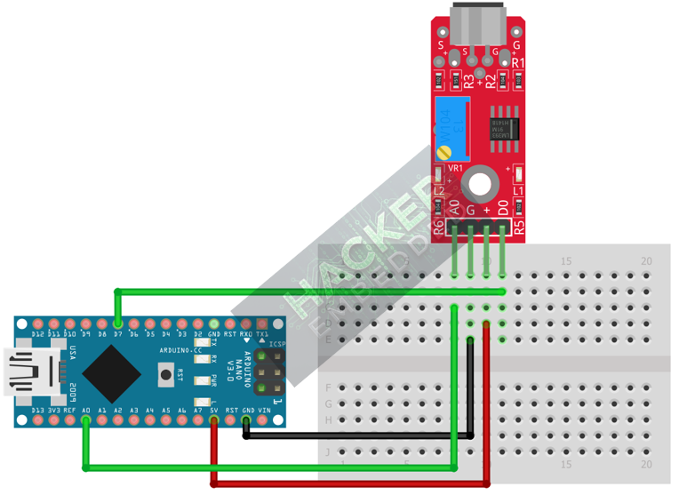
This image was created with Fritzing
Step 3 – Initialize Pin Modes
pinMode(7, INPUT); // D0 pin for digital ON/OFF detection
We will use the on-board LED (Pin 13) to reflect the digital trigger state.
4. Writing Dual-Mode Sound Sensing Code
We will sample the analog output quickly to find the peak volume (loudness) and use the digital output to monitor the set noise threshold.
Open main.ino and implement the following code.
					const int DIGITAL_PIN = 7; // D0 Output
const int ANALOG_PIN = A0; // A0 Output
const int LED_PIN = 13;    // Built-in LED

// Variables for monitoring the analog reading (Peak Amplitude)
const int CENTER_VALUE = 512; // Nominal ADC value (quiet)
int maxVolume = 0;
int minVolume = 1023;
int peakAmplitude = 0;

void setup() {
  pinMode(LED_PIN, OUTPUT);
  pinMode(DIGITAL_PIN, INPUT);
  Serial.begin(9600);
  Serial.println("KY-037 Sound Sensor Ready! Calibrate Digital Threshold.");
}

void loop() {
  // --- 1. Analog Reading (A0) - Find Peak-to-Peak Amplitude ---
  // Read 100 samples quickly to capture the waveform's peak and trough
  maxVolume = CENTER_VALUE;
  minVolume = CENTER_VALUE;

  // Quick 10ms sampling window
  long startTime = millis();
  while(millis() - startTime < 10) {
    int raw = analogRead(ANALOG_PIN);
    if (raw > maxVolume) {
      maxVolume = raw;
    } else if (raw < minVolume) {
      minVolume = raw;
    }
  }

  // Peak Amplitude is the range of the captured waveform
  peakAmplitude = maxVolume - minVolume;

  // --- 2. Read Digital State (D0) ---
  // Active LOW typically means noise detected (crossed the threshold)
  int digitalState = digitalRead(DIGITAL_PIN);

  // Control LED based on Digital Output (Action Trigger)
  if (digitalState == LOW) {
    digitalWrite(LED_PIN, HIGH); // Turn LED ON (Sound Detected)
  } else {
    digitalWrite(LED_PIN, LOW);  // Turn LED OFF (Quiet)
  }

  // Print both outputs to the Serial Monitor
  Serial.print("Analog (Amplitude): ");
  Serial.print(peakAmplitude);
  Serial.print(" | D0 State: ");

  if (digitalState == LOW) {
    Serial.println(">>> NOISE TRIGGERED (LOW) <<<");
  } else {
    Serial.println("QUIET (HIGH)");
  }

  delay(100);
}
Code Explanation
- Peak-to-Peak Amplitude: Instead of just reading the peak, we calculate peakAmplitude = maxVolume – minVolume. This value represents the total loudness and is more stable than just a single raw reading. A perfectly quiet room will result in an amplitude close to 0.
- Analog Reading: The base signal from the A0 pin should hover around 512 with no noise.
- D0 Output: The digital pin switches to LOW when the measured sound intensity (amplitude) exceeds the threshold set by the potentiometer.
5. Adjusting Sensitivity (Potentiometer)
The potentiometer on the KY-037 controls the sensitivity of the Digital Threshold for the D0 pin:
- Upload the code and open the Serial Monitor.
- Note the Analog (Amplitude) when the room is quiet (baseline). It should be a small number (e.g., 10-50).
- Make your target sound (e.g., a quiet whisper, a snap, or a clap). Note the peak amplitude reached.
- Adjust the Potentiometer:
- Increase sensitivity (counter-clockwise): The D0 pin will trigger on quieter sounds (smaller peak amplitudes).
- Decrease sensitivity (clockwise): The D0 pin will require a louder sound (larger peak amplitudes) to trigger.
- Calibrate: Find the sweet spot where only your intended sound triggers the Digital State.
6. Uploading and Running the Project
Step 1 – Build & Upload
Complete the standard build and upload process.
Step 2 – Test
- Calibrate the digital threshold using the potentiometer (Section 5).
- Quiet Room: The Arduino LED (Pin 13) should be OFF.
- Make Target Noise: When you make the noise that exceeds the calibrated threshold, the LED should turn ON and the Serial Monitor should show NOISE TRIGGERED.
7. Hands-On Lab Recap
You’ve learned:
- The operational difference between the Analog (A0) and Digital (D0) outputs of a high-sensitivity sound module.
- A robust technique for calculating peak-to-peak amplitude for accurate loudness measurement.
- The crucial skill of calibrating the digital threshold for sound detection.
This concludes the comprehensive series on fundamental KY-series modules.
8. Common Issues & Fixes
| Issue | Cause | Solution |
|---|---|---|
| Digital LED is always ON or never turns ON. | Potentiometer is mis-calibrated. | Calibrate the sensor carefully (Section 5). It must be set to separate the ambient noise baseline from the target sound's amplitude. |
| Analog reading is fixed near 512 and amplitude is near 0. | Faulty microphone or VCC/GND issue. | Check that VCC (5V) and GND are secure. If amplitude is 0 even with loud noise, the microphone may be broken. |
| Analog amplitude is too high even when quiet. | Room is not quiet, or sensor is too close to power cables. | Find a quieter area for testing. Keep the sensor away from electromagnetic interference. |

