ESP32 Tutorial: GPIO (Inputs/Outputs) and Basic Digital Control
Abstract
The General-Purpose Input/Output (GPIO) pins are the primary interface between the ESP32 microcontroller and the external world. This tutorial details how to configure these pins as either Digital Outputs (to control devices like LEDs) or Digital Inputs (to read signals from devices like buttons or switches) using the standard Arduino functions: pinMode(), digitalWrite(), and digitalRead(). We also highlight the critical pin restrictions unique to the ESP32.
1. Introduction
The ESP32 is a powerful, low-cost microcontroller renowned for its integrated Wi-Fi and Bluetooth capabilities, making it a favorite for IoT and embedded projects. At the core of its interaction with the external world are the General-Purpose Input/Output (GPIO) pins. These pins are the digital language interface, allowing the chip to control devices (like turning an LED on or off) and read signals from external components (like detecting a button press). Mastering the configuration and use of these pins is the foundational skill required for any ESP32 development.
This guide provides a comprehensive introduction to basic digital control on the ESP32 using the familiar Arduino framework. We will detail how to configure a pin as a Digital Output using pinMode(pin, OUTPUT) and control its state with digitalWrite(), and how to set a pin as a Digital Input to reliably read signals using digitalRead(). Crucially, we begin by outlining the architectural constraints specific to the ESP32, including pins dedicated to flash memory and those restricted to input-only use. Understanding these hardware limits is essential for building stable and functional projects from the start.
2. ESP32 GPIO Architecture and Constraints
The ESP32 features 48 programmable GPIO pins (General-Purpose Input/Output). Unlike many older microcontrollers, the ESP32 uses a flexible GPIO Matrix that allows most internal functions (like I2C, SPI, and PWM) to be mapped to almost any available GPIO pin.
However, several critical restrictions must be observed, especially on the common ESP32 WROOM modules, limiting it to 25 usable ones:
| Pin Restriction | Affected GPIOs | Notes |
|---|---|---|
| Input-Only Pins | GPIO 34, GPIO 35, GPIO 36, GPIO 39 | Cannot be set as outputs. They also lack internal pull-up/pull-down resistors. Use them only for reading external sensors. |
| Flash Memory Pins | GPIO 6 to GPIO 11 | These pins are internally connected to the integrated SPI flash memory and should not be used for external applications on most popular dev boards. |
| Voltage | All Pins | The ESP32 is a 3.3V logic device. Never connect its pins directly to 5V logic or power sources, as this will damage the chip. |
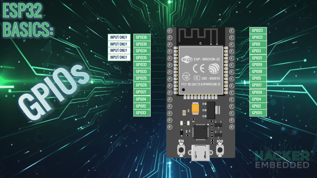
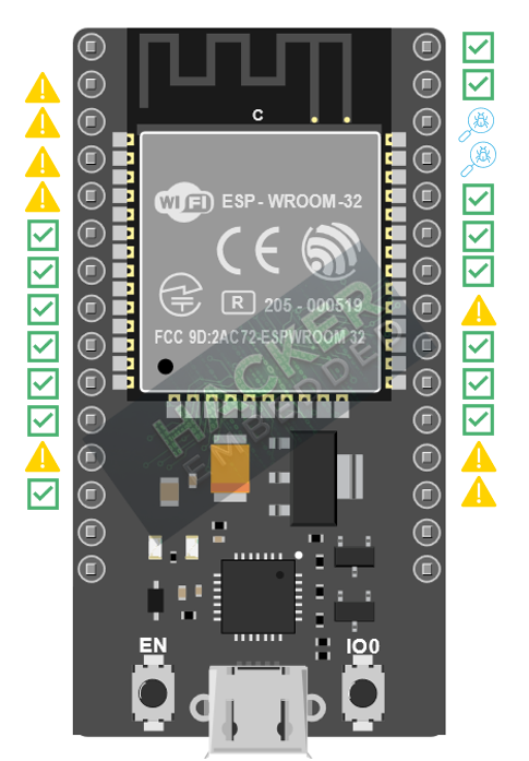
Here is a visual representation when it comes to use cases and limitations:
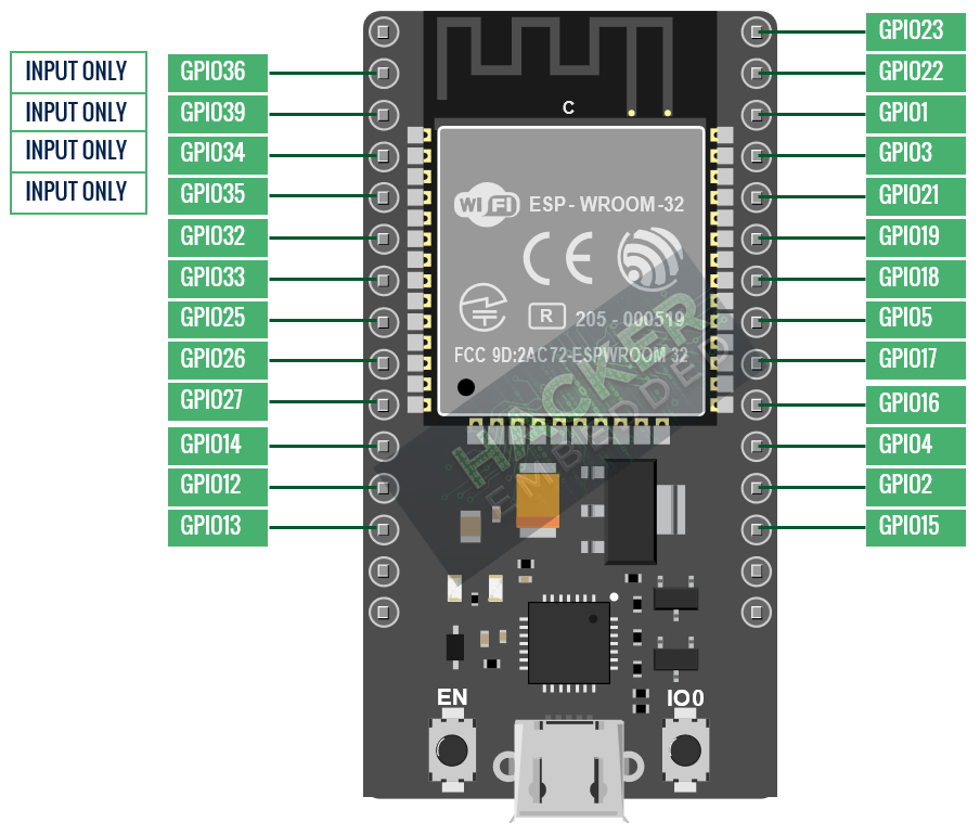
Here is the quick reference for the GPIO pins:
3. Configuring Digital Outputs (Controlling an LED)
To use a GPIO pin to control an external device, it must be configured as an output. Digital outputs produce a voltage level of HIGH (3.3V) or LOW (0V).
3.1 Functions for Output Control
- pinMode(pin, OUTPUT)
- Purpose: Sets the direction of the specified pin.
- Usage: Must be called once inside the setup()
- digitalWrite(pin, state)
- Purpose: Sets the voltage level of the output pin.
- Usage: Sets the pin to HIGH (3.3V, ON) or LOW (0V, OFF).
3.2 Digital Output Code Example (Blinking an LED)
We will use the onboard LED, typically connected to GPIO 2, to demonstrate output control.
					#define LED_PIN 2

void setup() {
  // Set the LED pin as an output
  pinMode(LED_PIN, OUTPUT);
}

void loop() {
  // Turn the LED ON (HIGH)
  digitalWrite(LED_PIN, HIGH);
  delay(500); // Wait 500 milliseconds

  // Turn the LED OFF (LOW)
  digitalWrite(LED_PIN, LOW);
  delay(500); // Wait 500 milliseconds
}
4. Configuring Digital Inputs (Reading a Button)
To read a signal from a device like a pushbutton, the GPIO pin must be configured as an input.
4.1 Input Modes and Pull Resistors
When a pin is configured as an input, it has extremely high impedance. If nothing is connected or the button is open, the pin is considered “floating” and can pick up random electrical noise, leading to unreliable readings. This is solved by using Pull-Up or Pull-Down resistors, or their internal equivalents.
| Mode | Function | When Button is Pressed |
|---|---|---|
| INPUT | Floating (Not recommended) | Unreliable |
| INPUT_PULLUP | Enables internal 45kΩ pull-up resistor (pin is HIGH by default). | Reads LOW (Connected to GND) |
| INPUT_PULLDOWN | Enables internal pull-down resistor (pin is LOW by default). | Reads HIGH (Connected to 3.3V) |
4.2 Functions for Input Reading
- pinMode(pin, INPUT_PULLUP)
- Purpose: Configures the pin as an input and enables the internal pull-up resistor.
- Hardware: Requires connecting the button between the GPIO pin and GND.
- digitalRead(pin)
- Purpose: Reads the current digital state of the configured input pin.
- Returns: HIGH (1) or LOW (0).
4.3 Digital Input Code Example (Button Toggles LED)
This sketch reads a button connected using a pull-up configuration and uses its state to control the onboard LED.
- Wiring: Connect the pushbutton between a chosen GPIO pin (e.g., GPIO 4) and GND.
					#define LED_PIN 2 // Onboard LED
#define BTN_PIN 4 // Button connected to GPIO 4 and GND

int buttonState = 0; // Variable to store the button state

void setup() {
  // Initialize the LED pin as an output
  pinMode(LED_PIN, OUTPUT);

  // Initialize the button pin as an input with internal pull-up enabled
  pinMode(BTN_PIN, INPUT_PULLUP);
}

void loop() {
  // Read the state of the button.
  // It reads LOW when pressed (since we used PULLUP)
  buttonState = digitalRead(BTN_PIN);

  if (buttonState == LOW) {
    // Button is pressed: Turn LED ON
    digitalWrite(LED_PIN, HIGH);
  } else {
    // Button is released: Turn LED OFF
    digitalWrite(LED_PIN, LOW);
  }
}
5. Lab Recap
You’ve learned the foundational steps for ESP32 digital control:
- The need to respect the Input-Only Pins (GPIO 34, 35, 36, 39) and avoid the Flash Pins (GPIO 6 to 11).
- How to configure a pin as a Digital Output using pinMode(pin, OUTPUT) to control devices like LEDs.
- How to control the state of an output pin using digitalWrite(pin, HIGH/LOW).
- The critical importance of using Pull-Up/Pull-Down resistors to prevent floating input states, accomplished in software with INPUT_PULLUP or INPUT_PULLDOWN.
- How to read the state of a digital input device, such as a button, using digitalRead(pin).

