ESP32 Tutorial: DAC and Audio | Generating True Analog Signals
Abstract
The Digital-to-Analog Converter (DAC) is the inverse of the ADC. It takes a digital value (a number) from the microcontroller and instantly converts it into a corresponding, precise analog voltage level. Unlike PWM, which only simulates an analog voltage by varying the duty cycle of a square wave, the DAC produces a true, steady analog DC voltage. This tutorial details the ESP32’s dual 8-bit DAC channels and demonstrates their use for generating simple voltage outputs and basic audio signals.
1. Introduction: DAC vs. PWM
While PWM is excellent for non-critical tasks like LED dimming or motor speed control, it’s unsuitable for applications requiring a smooth, stable DC voltage or high-quality audio reproduction. The DAC is designed for these tasks.
Feature | DAC (Digital-to-Analog Converter) | PWM (Pulse Width Modulation) |
Output Type | True, stable DC voltage (Analog) | Pulsed square wave (Digital Simulation) |
Resolution | 8 bits (0 to 255) | Configurable up to 16 bits (e.g., 0 to 4095) |
Fidelity | High fidelity (for audio, waveforms) | Low fidelity (requires filtering for stability) |
Purpose | Generating audio, reference voltages, smooth control | Dimming LEDs, controlling motors, generating heat |
ESP32 DAC Features
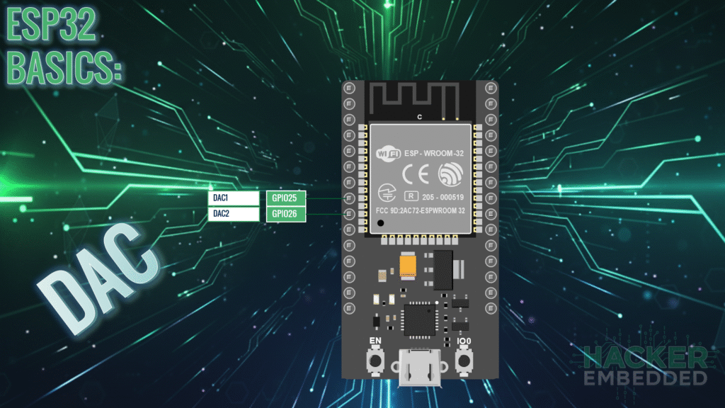
The ESP32 includes two independent, built-in 8-bit DAC channels:
- DAC Channel 1: Mapped to GPIO 25.
- DAC Channel 2: Mapped to GPIO 26.
Since the DAC is 8-bit, the output voltage is mapped to a value range of 0 to 255:
- Digital Value 0 = Analog Output 0V.
- Digital Value 255 = Analog Output 3V (VCC).
The voltage increment (resolution step) is approximately 3.3V/255≈12.94mV.
2. Core Function ESP32's DAC Control
Controlling the DAC is simple, requiring only the standard Arduino function dacWrite().
2.1 Function for DAC Output: dacWrite(pin, value)
This function outputs a stable voltage to the specified DAC pin.
- pin: Must be either GPIO 25 or GPIO 26.
- value: An integer between 0 and 255.
2.2 DAC Output Code Example (Generating a Steady Voltage)
This sketch continuously outputs a steady voltage of approximately 1.65V (half of 3.3V) on GPIO 25.
					#define DAC_PIN 25
#define HALF_VOLTAGE_VALUE 128 // 255 / 2 = 127.5, use 128

void setup() {
  Serial.begin(115200);
  Serial.println("Setting DAC to 1.65V (Value 128)");

  // No pinMode() needed; the DAC peripheral controls the pin directly.

  // Set the DAC output to the middle value (1.65V)
  dacWrite(DAC_PIN, HALF_VOLTAGE_VALUE);
}

void loop() {
  // Since the voltage is steady, the loop can be used for other tasks.
  delay(1000);
  Serial.println("DAC is stable at 1.65V...");
}
3. Generating Simple Audio (Sine Wave)
Audio is essentially a rapid sequence of voltage changes (an oscillating waveform). To generate sound, we must continuously write new DAC values to simulate a waveform like a sine wave.
3.1 Concept: Waveform Generation
A standard sine wave can be generated by looping through a pre-calculated array of 8-bit values (0-255). By writing these values to the DAC pin rapidly, the output voltage mimics the wave’s smooth oscillation.
3.2 Audio Generation Code Example (Sine Wave Tone)
This sketch generates a basic tone by cycling through a small sine wave lookup table.
#define AUDIO_PIN 25
#define FREQUENCY 440 // A4 note (440 Hz)
// Small sine wave lookup table (20 points for fast cycling)
// Values are biased up to center around 128 (1.65V)
const int SINE_LUT[] = {
128, 169, 203, 227, 240, 240, 227, 203, 169, 128,
87, 53, 29, 16, 16, 29, 53, 87
};
const int LUT_SIZE = 18; // The number of points in the array
void setup() {
// No setup needed for DAC pin other than the implicit setup via dacWrite
}
void loop() {
// Speed of the loop dictates the audio frequency
// Time = 1 / (Frequency * LUT_SIZE)
for (int i = 0; i < LUT_SIZE; i++) {
dacWrite(AUDIO_PIN, SINE_LUT[i]);
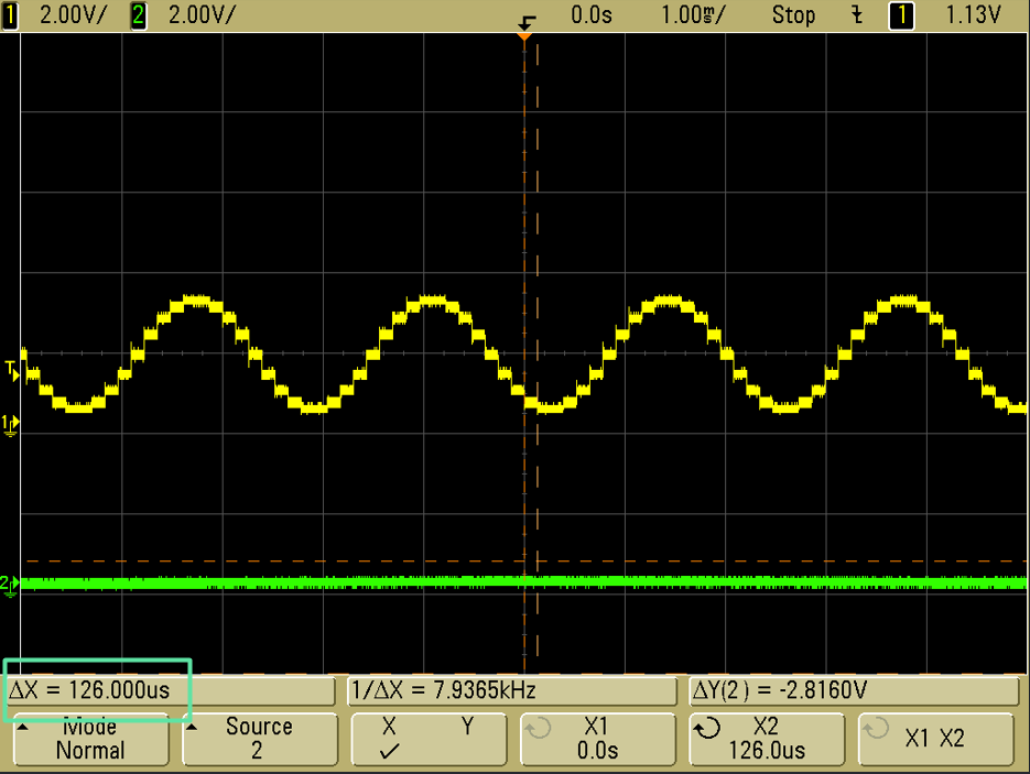
// Calculate the required delay in microseconds per sample
// For 440 Hz, Period = 1/440 Hz ≈ 2272 us.
// Delay per sample = Period / LUT_SIZE = 2272 us / 18 ≈ 126 us.
delayMicroseconds(126);
}
}
// NOTE: For practical audio, the I2S peripheral (not covered here) is preferred
// due to its ability to handle much higher sample rates. The DAC is best for
// simple tones or reference voltages.
4. Lab Recap
You’ve learned the basics of generating true analog output on the ESP32:
- The ESP32 features two 8-bit DAC channels on GPIO 25 and GPIO 26.
- The DAC generates a stable, true analog voltage, offering higher fidelity than PWM for audio and voltage referencing.
- The voltage range is 0V to 3.3V, mapped to the digital value range of 0 to 255.
- The output voltage is set using the function dacWrite(pin, value).
- Simple audio generation involves using the DAC to rapidly cycle through a waveform lookup table, with the speed of cycling determining the frequency of the generated tone.

