ESP32 Tutorial: PWM Tutorial
Abstract
Digital microcontrollers cannot generate true analog voltages, but they can simulate them using Pulse Width Modulation (PWM). This technique rapidly switches a digital pin ON and OFF to create a square wave. By varying the ratio of ON time (Duty Cycle) to total time, the effective average voltage is controlled, allowing devices like LEDs to be dimmed or DC motor speed to be regulated. This tutorial focuses on using the ESP32’s advanced LED Control (LEDC) peripheral to generate up to 16 independent PWM signals using the Arduino framework.
1. Introduction
To dim an LED, you need less current flowing through it. While analog microcontrollers use a Digital-to-Analog Converter (DAC) to directly output a variable voltage, the ESP32 (and Arduino) use PWM on digital output pins to achieve the same result visually.
Understanding PWM
- Pulse: The output signal is a square wave that alternates between 3.3V (ON or HIGH) and 0V (OFF or LOW).
- Period: The total time for one complete ON-OFF cycle. The inverse of the period is the Frequency (Hz).
- Duty Cycle: The percentage of the period for which the signal is ON (HIGH).
- 0% Duty Cycle: Always LOW (0V effective voltage, LED OFF).
- 50% Duty Cycle: HIGH for half the period (1.65V effective voltage, LED half-brightness).
- 100% Duty Cycle: Always HIGH (3.3V effective voltage, LED full brightness).
ESP32 LEDC (PWM) Controller
The ESP32 uses a dedicated hardware peripheral called the LED Control (LEDC) peripheral for PWM. This provides significant advantages over the simpler PWM on the Arduino Uno:
- Channels: Up to 16 independent PWM channels (0-15).
- Resolution: Configurable up to 16 bits. A 10-bit resolution (0-1023) is commonly used.
- Frequency: Up to 40 MHz.
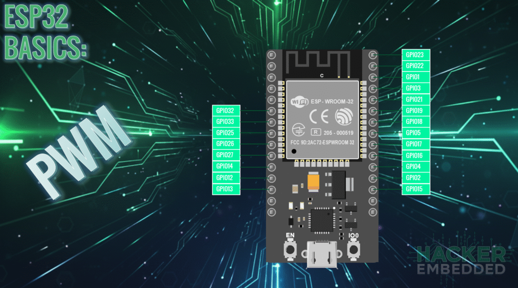
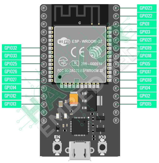
- Pinout:
2. Core Function for ESP32 PWM
Since the ESP32 uses the LEDC peripheral, you must use specific functions to set up and control the PWM signal, rather than the simpler analogWrite() used on standard Arduino boards.
2.1 Setup Functions (In setup())
To initialize PWM, you must define the channel, frequency, and resolution:
- ledcSetup(channel, frequency, resolution_bits)
- Purpose: Configures a PWM channel.
- channel: 0 to 15. Choose any free channel.
- frequency: The speed of the PWM signal (e.g., 5000 Hz or 5 kHz).
- resolution_bits: The number of bits for the duty cycle register (e.g., 8, 10, or 12). If you use 10 bits, the duty cycle range will be 0 to 1023.
- ledcAttachPin(gpio_pin, channel)
- Purpose: Maps the configured PWM channel to a physical GPIO pin.
- gpio_pin: Any valid output GPIO pin on the ESP32 (e.g., GPIO 4).
2.2 Control Function (In loop())
- ledcWrite(channel, duty_cycle)
- Purpose: Sets the brightness/power level (duty cycle) for the channel.
- channel: The channel number previously configured.
- duty_cycle: An integer value based on your set resolution. If resolution is 10 bits, the range is 0 to 1023.
3. Hands-On Lab: Fading an LED with PWM
This lab demonstrates how to set up and use PWM to create a smooth fading effect on an LED.
ESP32 PWM Code Example
					// Define the GPIO pin and PWM parameters
const int ledPin = 2;           // The GPIO pin the LED is connected to
const int frequency = 5000;     // 5 KHz frequency
const int resolution = 10;      // 10-bit resolution (Duty cycle range 0-1023)
const int maxDuty = 1023;       // Max value for 10-bit resolution

void setup() {
  // 1. Configure the PWM channel
  // Parameters: channel, frequency, resolution
  ledcAttach(ledPin, frequency, resolution);
}

void loop() {
  // Fade IN (Increase brightness from 0 to maxDuty)
  for (int dutyCycle = 0; dutyCycle <= maxDuty; dutyCycle += 5) {
    // Write the new duty cycle value
    ledcWrite(ledPin, dutyCycle);
    delay(5); // Small delay for visual effect
  }

  // Fade OUT (Decrease brightness from maxDuty to 0)
  for (int dutyCycle = maxDuty; dutyCycle >= 0; dutyCycle -= 5) {
    // Write the new duty cycle value
    ledcWrite(ledPin, dutyCycle);
    delay(5); // Small delay for visual effect
  }
}
Execution Steps
- Upload the sketch to your ESP32 board.
- Observe the LED fading effect
4. Lab Recap
You’ve learned the essential steps for simulating analog output with ESP32 PWM:
- PWM uses a variable Duty Cycle to create an effective average voltage for analog control.
- The ESP32 utilizes the LEDC hardware peripheral, providing up to 16 high-resolution PWM channels.
- You must configure the PWM channel using ledcAttach(gpio_pin, frequency, resolution) before use.
- The brightness or power level is set using ledcWrite(gpio_pin, duty_cycle), where the duty_cycle value depends on the resolution set in ledcAttach().

