ESP32 Tutorial: I2C Communication | Inter-Integrated Circuit
Abstract
I2C (Inter-Integrated Circuit), pronounced “I-squared-C” or “I-two-C,” is a widely used serial communication protocol that allows a single microcontroller (the Master) to communicate with multiple peripheral devices (the Slaves or sensors/modules) over just two wires. The ESP32 supports two independent I2C interfaces and is highly flexible, allowing almost any GPIO pin to be configured as the I2C clock or data lines. This tutorial covers the fundamental wiring, configuration, and code structure for setting up the ESP32 as an I2C Master using the Arduino Wire library.
1. Introduction: The Two-Wire Bus
I²C is a multi-master, multi-slave serial bus developed by Philips (now NXP). It requires only two signal lines:
- SDA (Serial Data Line): The bidirectional line used for transferring data between the Master and Slaves.
- SCL (Serial Clock Line): The line controlled by the Master to synchronize data transfer.
1.1 Key I2C Requirements
- Pull-up Resistors: Both the SDA and SCL lines must be connected to the power supply (usually 3V on the ESP32) using pull-up resistors (typically 4.7 kΩ or 10 kΩ). These resistors keep the lines HIGH when idle, as the devices only pull the lines LOW to signal data.
- Slave Addresses: Every device on the I²C bus must have a unique 7-bit address (0 to 127). The Master uses this address to specify which Slave it wants to talk to.
- Flexibility on ESP32: Unlike some microcontrollers with fixed I²C pins, the ESP32’s multiplexing capability means you can define any available GPIO pins (that aren’t reserved or input-only) as the SDA and SCL lines.
2. Wiring and Pin Selection
While the ESP32 is flexible, standard practice often uses designated pins for I²C to maintain consistency.
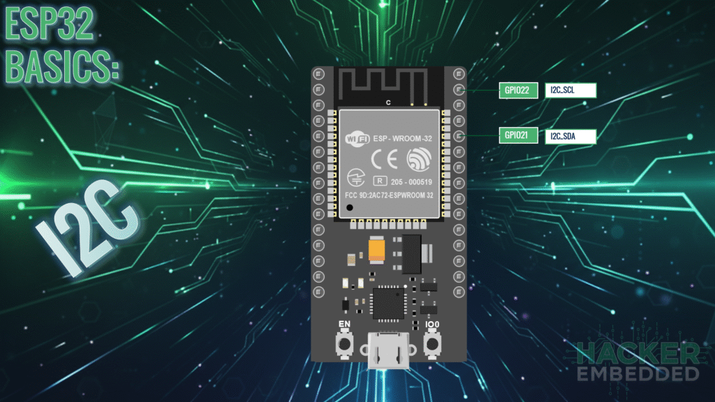
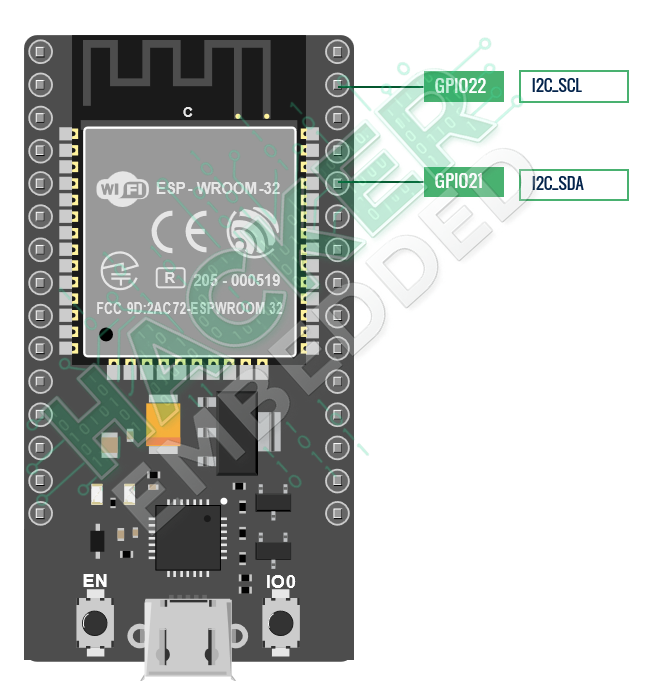
Common ESP32 I²C Pin Assignments
Pin Function | Recommended GPIO (Default) | Notes |
SDA (Data) | GPIO 21 | Used for sending/receiving data. |
SCL (Clock) | GPIO 22 | Used for synchronizing communication. |
Connection: Connect the SDA pin on the ESP32 to the SDA pin on the sensor, and the SCL pin on the ESP32 to the SCL pin on the sensor. Connect both lines to 3.3V via pull-up resistors.
3. Core Functions for I2C Communication
The Arduino framework uses the Wire library (inherited from the standard Arduino core) for I²C communication.
3.1 Setup: Wire.begin()
The begin() function initializes the I²C interface and sets the GPIO pins.
					#include <Wire.h>

// Initialize I2C, setting GPIO 21 as SDA and GPIO 22 as SCL
Wire.begin(21, 22);
3.2 Data Transfer: Write (Master to Slave)
To send data to a slave device (e.g., configuring a sensor register):
- Start Transmission: Wire.beginTransmission(slaveAddress)
- Send Data: Wire.write(byteOrRegister)
- End Transmission: Wire.endTransmission()
3.3 Data Transfer: Read (Master from Slave)
To request and receive data from a slave device (e.g., reading temperature):
- Request Bytes: Wire.requestFrom(slaveAddress, numBytes)
- Check Available: Wire.available() (returns the number of received bytes)
- Read Bytes: Wire.read() (reads one byte at a time)
4. Hands-On Lab: I2C Scanner
Before reading any specific sensor, you must confirm the correct I²C address. This sketch scans all possible I²C addresses (1 to 127) and reports any active devices.
4.1 ESP32 I²C Scanner Code Example
					#include <Wire.h>

// Define the I2C pins used on the ESP32
#define I2C_SDA 21
#define I2C_SCL 22

void setup() {
  Serial.begin(115200);
  delay(1000);

  // Initialize I2C Master on the defined pins
  Wire.begin(I2C_SDA, I2C_SCL);
  Serial.println("\nI2C Scanner Initialized...");
  Serial.println("Scanning for devices...");
}

void loop() {
  byte error, address;
  int deviceCount = 0;

  Serial.println("-------------------------------------");

  for (address = 1; address < 127; address++) {
    // Begin transmission to the current address
    Wire.beginTransmission(address);

    // The endTransmission() function returns 0 if the device acknowledges
    // the address (i.e., if a device exists at that address).
    error = Wire.endTransmission();

    if (error == 0) {
      Serial.print("I2C device found at address 0x");

      // Print the address in hexadecimal format
      if (address < 16)
        Serial.print("0");
      Serial.println(address, HEX);

      deviceCount++;
    }
    // Else, if error is 4, it means an unknown error occurred
    else if (error == 4) {
      // Ignore general errors for the purpose of a simple scanner
    }
  }

  if (deviceCount == 0) {
    Serial.println("No I2C devices found.");
  } else {
    Serial.print("Scan complete. Total devices found: ");
    Serial.println(deviceCount);
  }

  // Only scan once every 5 seconds
  delay(5000);
}
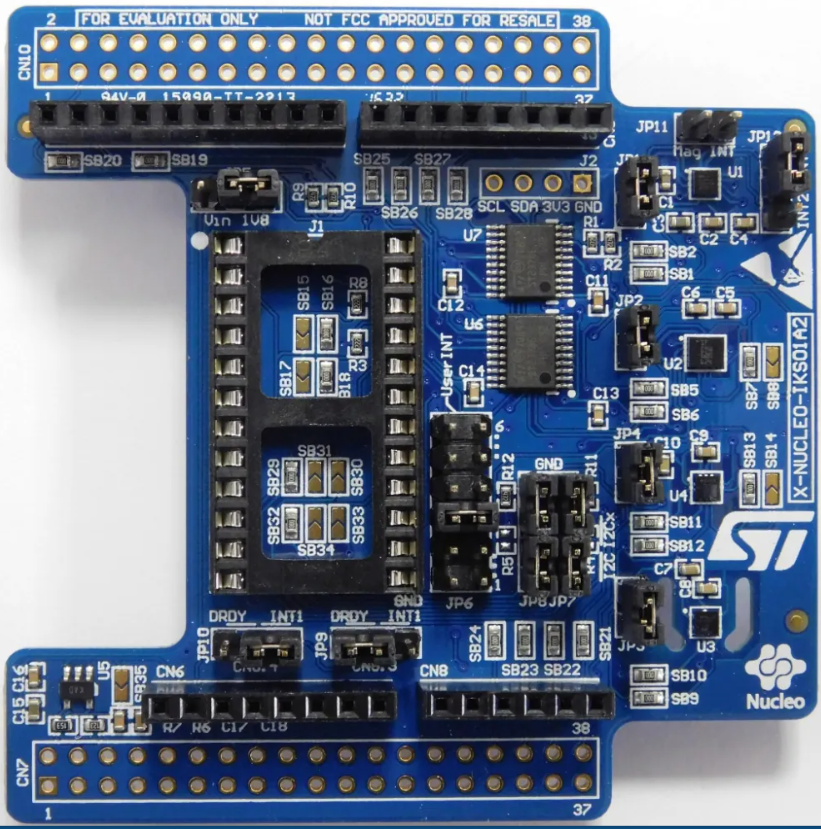
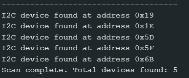
The following message is shown after connecting the X-NUCLEO-IKS board:
4.2 Code Explanation: ESP32 I²C Device Scanner
This program is a crucial diagnostic tool for any I²C project. Its goal is to act as an I²C Master and systematically check every possible slave address on the bus to determine which ones are active, ensuring proper communication setup before interacting with a specific sensor.
4.3 Core Mechanism
The code iterates through all 127 possible 7-bit I²C slave addresses (1 to 127). For each address, it attempts a minimal communication sequence. If the slave device exists and responds with an acknowledgment (ACK), the address is printed to the Serial Monitor.
4.4 Execution Outcome
Since the loop() function executes the entire scan every 5 seconds, the user sees a periodic report in the Serial Monitor:
First Run: Prints a list of active I²C addresses .
Absence of Devices: If nothing is connected or the wiring/pull-up resistors are wrong, it will print:
"No I2C devices found."Goal Achieved: By successfully running the scan, the user confirms the SDA/SCL wiring is correct and obtains the exact slave address needed to communicate with their sensor in subsequent code.
5. Lab Recap
You’ve learned the essentials of setting up I²C communication on the ESP32:
- I²C uses two lines: SDA (Data) and SCL (Clock), and requires pull-up resistors on both lines.
- The ESP32 is highly flexible, allowing you to use almost any GPIO pin for I²C by specifying them in begin(SDA_pin, SCL_pin).
- All slave devices on the bus must have a unique address.
- The scanner code uses beginTransmission() and Wire.endTransmission() to probe for a device’s address, with a return value of 0 indicating success.

