ESP32 Tutorial: Low Power Modes | Maximizing Battery Life
Abstract
For most Internet of Things (IoT) projects, the ESP32 spends the vast majority of its time waiting for an event (like a sensor reading, a button press, or a network packet). Running the CPU at full speed during this idle time drains the battery quickly. The ESP32 offers several sophisticated Low Power Modes to drastically reduce energy consumption by selectively turning off components. This tutorial focuses on the three main sleep modes: Light Sleep, Deep Sleep, and Hibernation and how to implement them to maximize the lifespan of battery-powered devices.
1. Introduction: The Power Saving Imperative
Battery-powered ESP32 devices often need to run for months or years. Moving from the default Active Mode (drawing 80-150 mA) to sleep modes can reduce consumption to a few microamperes (μA).
The key to power management is the Real-Time Clock (RTC) co-processor, a low-power internal unit that can run independently while the main CPU and most peripherals are powered down. The RTC is essential for waking the chip back up.
ESP32 Sleep Mode Comparison
Mode | Main CPU State | RTC State | Power Consumption | Wakeup Time |
Active | ON | ON | Highest (80-150 mA) | N/A |
Modem Sleep | ON (but Wi-Fi/BT OFF) | ON | Low (20-80 mA) | Instant |
Light Sleep | Suspended (RAM kept) | ON | Very Low (≈0.8 mA) | Fast (ms) |
Deep Sleep | Powered OFF (RAM lost) | ON | Extremely Low (≈10−50μA) | Slow (seconds, requires reboot) |
Hibernation | Powered OFF | OFF | Lowest (≈5μA) | Slowest (requires reboot) |
2. Light Sleep Mode: Quick Wakes and RAM Retention
Light Sleep is ideal when you need to retain the program state (variables in RAM) but need to wake up quickly upon an external event or a short timer. The main CPU is paused, but all data in its SRAM is retained.
2.1 Wakeup Sources for Light Sleep
- Timer: Set a duration after which the ESP32 should wake up.
- External Interrupt: A signal change on an RTC GPIO (any pin connected to the RTC domain, such as GPIO 12-15, 25-27, 32-39).
- Touch Sensor: A change in capacitance on a touch pin.
2.2 Core Function: esp_sleep_enable_timer_wakeup()
While setCpuFrequencyMhz() is used for runtime clock speed change, the primary function for entering Light Sleep is to first configure the wakeup source and then call the sleep function.
					#include "esp_sleep.h"

// 1. Set the wakeup time (e.g., 5 seconds)
// Time is in microseconds
esp_sleep_enable_timer_wakeup(5 * 1000000);

// 2. Enter Light Sleep mode
// This command pauses the CPU until the wakeup source triggers.
esp_light_sleep_start();
3. Deep Sleep Mode: The Ultimate Power Saver
Deep Sleep is the most common and effective low-power mode for battery applications. The main CPU is powered off, and all data in the fast SRAM is lost. Only the small RTC Fast Memory retains data, along with the RTC timer and its peripherals. Waking from Deep Sleep is essentially a full system reboot, making it suitable for “measure, connect, send data, and go back to sleep” cycles.
3.1 Wakeup Sources for Deep Sleep
- Timer: The most common method, allowing the chip to wake up periodically.
- External Wakeup (EXT0/EXT1):
- EXT0: Triggered by a single RTC GPIO pin (e.g., connected to a pushbutton).
- EXT1: Triggered by multiple RTC GPIO pins using a mask (e.g., using a touch sensor array).
- Touch Sensor: A touch event wakes the system.
3.2 Hands-On Lab: Deep Sleep with Timer Wakeup
This example puts the ESP32 into Deep Sleep for 10 seconds. We use a global RTC memory variable to persist a boot count across reboots, as regular variables are lost.
					#include "esp_sleep.h"

// Variable stored in RTC memory (persists through Deep Sleep reboots)
// '__attribute__((section(".rtc.data")))' is a GCC specific attribute
// that ensures the variable is placed in the RTC memory region.
RTC_DATA_ATTR int bootCount = 0;

void setup() {
  Serial.begin(115200);
  delay(100); // Give time for the Serial port to initialize

  // Increment boot count every time the chip wakes up
  bootCount++;

  Serial.print("Boot #");
  Serial.println(bootCount);
  Serial.println("Starting measurement and sending data...");


  // Set the wakeup time (e.g., 5 seconds)
  // Time is in microseconds

  Serial.println("Enter Light Sleep mode for 5 seconds...");
  esp_sleep_enable_timer_wakeup(5 * 1000000);
  // Enter Light Sleep mode
  // This command pauses the CPU until the wakeup source triggers.
  esp_light_sleep_start();


  // --- Configure Deep Sleep ---
  Serial.println("Going to Deep Sleep for 10 seconds...");
  // 1. Set the wakeup source to a timer for 10 seconds
  // Time is in microseconds: 10 * 1,000,000
  esp_sleep_enable_timer_wakeup(10 * 1000000);

  // 2. Enter Deep Sleep
  // This command immediately shuts down the CPU.
  esp_deep_sleep_start();
}

void loop() {
  // This code will never run because the chip goes to sleep in setup()
}
3.3 Code Explanation: ESP32 Dual-Mode Sleep Tester
This program demonstrates the use of both Light Sleep and Deep Sleep modes on the ESP32, focusing on maximizing power saving while showing how to maintain data persistence across the Deep Sleep-induced reboot cycle.
3.4 Goal: Persistent Boot Counter and Dual Sleep Test
The primary goal is to implement a boot counter that survives the low-power Deep Sleep cycle, proving that the RTC Memory retains data even when the main CPU is powered off. The code then sequentially tests Light Sleep and Deep Sleep to show their implementation.
3.5 Execution Flow (Step-by-Step)
The code is contained entirely within the setup() function because the chip is programmed to enter sleep modes rather than running an infinite loop().
| Step | Code Action | Result and Power State |
| 1. Initialization | bootCount++; and Serial.println(bootCount); | The counter is incremented (e.g., from 0 to 1 on the first run). The current boot number is printed to the serial monitor. |
| 2. Light Sleep | esp_sleep_enable_timer_wakeup(5 * 1000000); followed by esp_light_sleep_start(); | The chip pauses for 5 seconds. The main CPU goes to a low-power state, but the RAM content is retained. After 5 seconds, the CPU immediately resumes execution at the next line of code. |
| 3. Deep Sleep Configuration | esp_sleep_enable_timer_wakeup(10 * 1000000); | The RTC timer is re-configured to trigger a wakeup after 10 seconds. This overwrites the previous 5-second setting. |
| 4. Deep Sleep Entry | esp_deep_sleep_start(); | The main CPU is immediately powered off. Power consumption drops to the microamp range (µA). The bootCount is retained in the RTC memory. |
| 5. Wakeup Cycle | (10 seconds pass) | The RTC timer triggers a full system reboot. The chip restarts, and execution returns to the beginning of the setup() function (Step 1). The bootCount is read from the RTC memory, increments (e.g., from 1 to 2), and the whole process repeats. |
The loop() function will never be reached because the system either pauses in Light Sleep or reboots entirely upon waking from Deep Sleep.
3.6 Execution Steps
- Upload the sketch.
- Open the Serial Monitor.
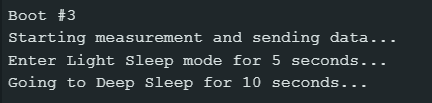
- The chip will print Boot #1 and then immediately go to sleep for 5 and 10 seconds, using both light sleep and deep sleep.
- After 10 seconds, the RTC timer will trigger a reboot. The chip will then print Boot #2, demonstrating that the bootCount was successfully saved in the RTC memory and that the timer successfully triggered the wake-up.
4. Lab Recap
You’ve learned how to harness the ESP32’s power-saving modes:
- Light Sleep saves power while retaining RAM, allowing for fast wakeups.
- Deep Sleep offers the lowest power consumption (μA range) but results in a full reboot upon waking.
- Data needed to persist across Deep Sleep cycles must be stored in RTC memory using the RTC_DATA_ATTR
- The functions esp_sleep_enable_timer_wakeup() and esp_deep_sleep_start() are the primary tools for entering Deep Sleep mode.

