ESP32 Tutorial: Timers and Timer Interrupt | Non-Blocking Time Management
Abstract
When precise, repetitive actions need to occur at specific intervals—such as reading a sensor every 500ms or toggling an LED every second—relying on the delay() function blocks the entire program, preventing the ESP32 from performing other critical tasks like managing Wi-Fi or monitoring inputs. Timers are specialized hardware peripherals that run independently of the CPU and provide a non-blocking, accurate way to manage time. This tutorial covers how to configure the ESP32’s hardware timers to trigger a Timer Interrupt at set intervals.
1. Introduction: The Problem with delay()
The main difference between time management in the basic loop() and using hardware timers is one of control:
- delay(): Pauses all CPU execution. The code is stuck and cannot react to external events (like a button press or an incoming network packet).
- Hardware Timer: The CPU continues running the loop(). The timer runs in the background and, when its count expires, it triggers a non-blocking Timer Interrupt, running a quick Interrupt Service Routine (ISR), then immediately returning control to the main program. This is crucial for real-time, multitasking IoT applications.
ESP32 Timer Features
The ESP32 includes two Timer Groups (T0 and T1), each containing two 64-bit general-purpose timers (totaling four timers).
- 64-bit Counter: Provides extremely long timing periods with high precision.
Programmable Prescaler: Divides the main clock frequency to set the timer’s tick rate, allowing the timer to be configured from microsecond resolution up to minutes or hours.
2. Core Function for ESP32 Interrupts
To achieve an exact interrupt interval, you must correctly configure the timer’s clock source and prescaler.
2.1 ESP32 Core Clock Frequency
The general-purpose timers in the ESP32 are clocked by the 80MHz APB (Advanced Peripheral Bus) clock. This is the base frequency for your timer calculations.
- Base Clock Frequency (F_CLK): 80MHz
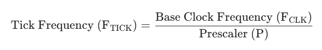
2.2 The Prescaler and Tick Rate
The Prescaler (P) divides the base clock frequency to slow down the counter, determining the timer’s tick rate. The tick is the smallest unit of time the timer can measure.
For microsecond resolution (a 1MHz tick frequency), we need the Prescaler to be 80:
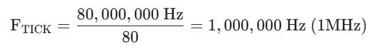
- A 1MHz tick frequency means 1,000,000 ticks occur every second. Therefore, 1 tick = 1 microsecond.
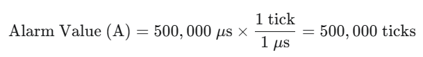
2.3 Calculating the Alarm Value
The Alarm Value (A) is the total number of ticks the timer must count up to before triggering the interrupt.

If the desired interval is 500ms and the Tick Frequency is 1MHz:
3. Core Functions for Timer Interrupts
The ESP32 Arduino Core provides a structured, high-level approach to using the hardware timers. The process involves creating a timer object, defining its behavior, and starting it.
3.1 Creating and Configuring the Timer Object
First, you need to include the necessary library and create an instance of the timer object:
#include <ESP32-Timer-Interrupt.h> // Library for easier timer management
// or using the built-in system timer functions if available
When using system timer functions, the setup is typically handled by three main functions, more details available on ESP API Timer – – — Arduino ESP32 latest documentation:
– timer = timerBegin(frequency)
- Purpose: select timer frequency in Hz. Sets how quickly the timer counter is “ticking”.
– timerAttachInterrupt(timer, ISR_function)
- Purpose: Associates the timer with the ISR function.
- ISR_function: The name of the function to be called when the timer expires.
– timerAlarmWrite(timer, time_in_microseconds, autoreload_flag, reload_count)
- Purpose: This function is used to configure alarm value and autoreload of the timer. Alarm is automatically enabled.
- time_in_microseconds: The duration before the interrupt fires (e.g., 500,000 for 500ms).
- autoreload_flag: Set to true to make the timer automatically reset and fire again.
- reload_count: number of autoreloads (0 = unlimited). Has no effect if autorealod is disabled.
3.2 Timer Interrupt Service Routine (ISR)
Similar to external GPIO interrupts, the Timer ISR must adhere to strict rules:
- Rule 1: Use volatile All variables modified in the ISR and used in the loop() must be declared volatile.
- Rule 2: Keep it concise. The function must be quick. Only critical, minimal logic (like toggling a flag or incrementing a counter) is performed here.
4. Hands-On Lab: Non-Blocking LED Blink
This lab demonstrates how to use a hardware timer to blink an LED precisely every 500 milliseconds (0.5 seconds) without using the delay() function, leaving the main loop() free for other tasks.
ESP32 Timer Code Example
We will use the standard C function calls for the ESP32 IDF abstraction available in the Arduino Core (using esp_timer.h which is often abstracted into soc/timer_group_struct.h and helper functions):
					// ------------------------------------
// 1. DEFINITIONS AND GLOBAL VARIABLES
// ------------------------------------
#include <Arduino.h>
// Variables shared between timer ISR and loop() must be declared volatile
int interruptCounter = 0;
bool ledState = LOW;
hw_timer_t * timer = NULL; // Pointer to the timer object

#define LED_PIN 2           // ESP32's built-in LED (GPIO2)
#define TIME_BASE 1000000   // 1MHz tick rate (1 tick = 1 microsecond)
#define ALARM_VALUE 500000  // 500,000 ticks = 500,000 us = 500 ms (0.5s)

// ------------------------------------
// 2. TIMER INTERRUPT SERVICE ROUTINE (ISR)
// ------------------------------------
// IRAM_ATTR is crucial for stability on ESP32
void IRAM_ATTR onTimer() {
    interruptCounter++;
    // Toggle LED state every time the ISR runs (every 500ms)
    ledState = !ledState;
}

// ------------------------------------
// 3. SETUP FUNCTION
// ------------------------------------
void setup() {
    Serial.begin(115200);
    pinMode(LED_PIN, OUTPUT);
    digitalWrite(LED_PIN, LOW); // Start with LED off

    // 1. Initialize the timer (Timer 0 in Group 0)
    // Parameters: timer_num (0-3), prescaler, count_up (true)
    // The ESP32 core often uses internal timer management, so 0 is usually fine.
    timer = timerBegin(TIME_BASE); // API 3.0 setup timer for 1uSec

    // 2. Attach the interrupt function (ISR) to the timer
    // Parameters: timer, ISR_function
    timerAttachInterrupt(timer, &onTimer);

    // 3. Set the alarm (ALARM_VALUE) and enable auto-reload
    // Set alarm to call onTimer function every half second (value in microseconds).
    // Repeat the alarm (third parameter) with unlimited count = 0 (fourth parameter).
    timerAlarm(timer, ALARM_VALUE, true, 0);
}

// ------------------------------------
// 4. MAIN LOOP FUNCTION
// ------------------------------------
void loop() {
    // CRITICAL LOGIC: Use the flag set by the ISR to control the LED
    digitalWrite(LED_PIN, ledState);

    // Print a status message every second, demonstrating non-blocking
    // Since the ISR runs every 500ms, we check after 2 executions (1 second)
    if (interruptCounter >= 2) {
        Serial.print("Loop is running. Timer Count: ");
        Serial.println(interruptCounter);
        // Safely reset the counter after reading
        interruptCounter = 0;
    }
    // The loop continues to run at full speed, processing this check and any
    // other tasks (like Wi-Fi) without waiting for the timer to expire.
}
Execution Steps
- Upload the sketch to your ESP32 board.
- Open the Serial Monitor at 115200 baud.
- The onboard LED will begin to blink at a precise 500ms interval.
- The Serial Monitor will print a message approximately every 1 second. The fact that the printing continues without interruption proves that the LED blinking is being handled by the independent hardware timer, not by a blocking delay() in the loop().
5. Lab Recap
You’ve learned how to implement non-blocking time control using the ESP32’s hardware timers:
- Hardware Timers are essential for multitasking and achieving precise, non-blocking timing, unlike the blocking delay()
- The ESP32 provides four 64-bit general-purpose timers across two groups.
- The timer must be initialized with timerBegin(), linked to an ISR with timerAttachInterrupt(), and configured for an interval using timerAlarmWrite().
- The Timer Interrupt Service Routine (ISR) must be brief and quick, and any shared variables are recommended to be declared as volatile.
- The Prescaler is used to adjust the timer’s tick frequency, allowing accurate time measurement down to the microsecond level.

