STM32 Tutorial: STM32 System Bootloader
Abstract
Every STM32 developer knows the frustration of a “bricked” board or the challenge of implementing field firmware updates. At the heart of solving these issues lies the STM32 System Bootloader. This article provides a deep dive into the STM32 boot sequence based on the AN2606 standard, explaining how the hardware transitions from power-on to code execution. We explore the critical roles of Boot Pins and Option Bytes in memory mapping and demonstrate a hands-on workflow using the AN3155 USART protocol. By leveraging STM32CubeProgrammer, you will learn how to interface with the built-in bootloader to recover, program, and secure your microcontrollers without the need for an external JTAG/SWD debugger.
1. Introduction
Understanding the system boot process is critical for firmware design, debugging, and secure applications. Unlike many microcontrollers that only offer a “blank” start, STM32 chips come pre-programmed from the factory with a system bootloader. This code resides in a read-only section of the memory and allows the MCU to be programmed over standard interfaces like UART, SPI, I2C, USB, or CAN/FDCAN.
The primary reference for this system boot is described in the AN2606: “STM32 system memory boot mode.” Whether you are designing a custom PCB or troubleshooting a development kit, knowing how the MCU selects its startup memory, be it Flash, SRAM, or System Memory, is essential.
2. Prerequisites
Before starting the programming and validation process, ensure you have the following:
STM32CubeProgrammer Installed
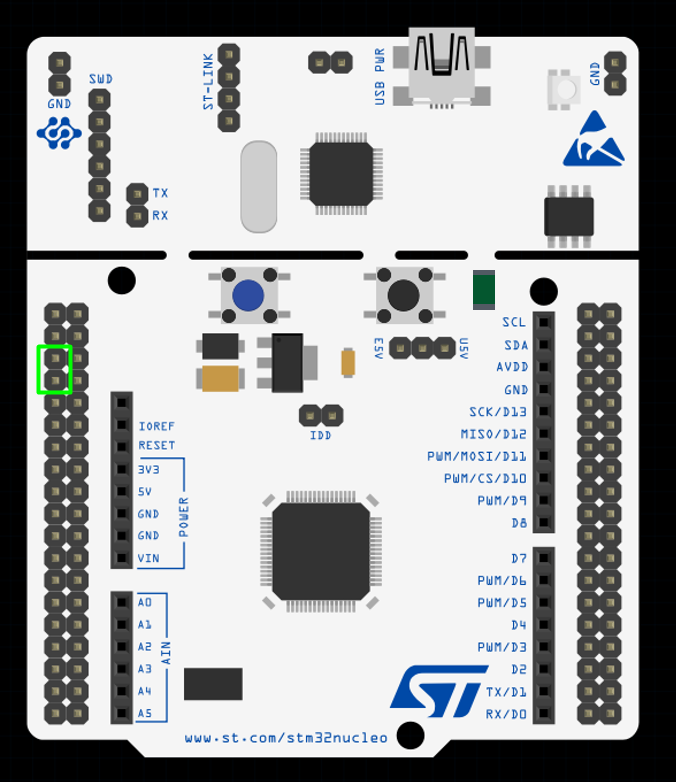
Target STM32 Device: The microcontroller board must be connected via a debug probe (ST-Link, J-Link, etc.). We’ll use the classic NUCLEO board for this.
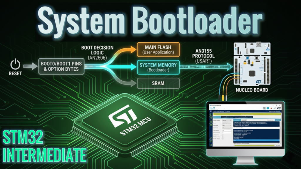
3. STM32 System Bootloader Sequence Overview
When an STM32 undergoes a reset (Power-on, Reset pin, or Software reset), the hardware looks at specific configuration bits to decide where to start executing code.
The Standard Boot Pattern
For the majority of classic STM32 families (like the G0, F1, F4, and L1), the boot mode is selected via physical BOOT0 pin and BOOT1 via option byte:
BOOT0 | BOOT1 | Boot Memory | Description |
0 | X | Main Flash | Normal operation: Boots your firmware. |
1 | 0 | System Memory | Enters the factory bootloader. |
1 | 1 | SRAM | Executes code from RAM (used for specialized debugging). |
Important Variation: Activation Patterns
It is important to note that not all STM32s are the same and follow this exact sequence. As the ecosystem has evolved, ST has now almost 20 different “Bootloader activation patterns” and the AN2606 provides the extensive detailed list (the document is 500+ page long) of the system boot features, pins and known limitation for all STM32 series and families. Some newer devices (like the STM32G0 or H7) might not have a BOOT1, or they may rely entirely on Option Bytes (software configuration) rather than physical pins.
Pro Tip: Always consult Table 2 in AN2606, titled “Bootloader activation patterns,” for your specific part number. It details the exact pin states and Option Byte settings required to trigger the bootloader.
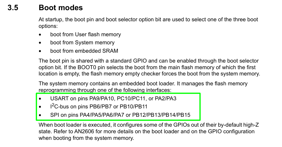
4. System Memory & Communication Protocols
The System Memory bootloader is a permanent firmware that supports various communication protocols depending on the MCU family. Once the bootloader is active, it “listens” on specific pins for a connection.
To understand the low-level details of how your programming tool talks to the chip, refer to the protocol-specific Application Notes:
The datasheet contains the pins and interfaces available for a given STM32 series, that act as a quick reference for the bootloader:
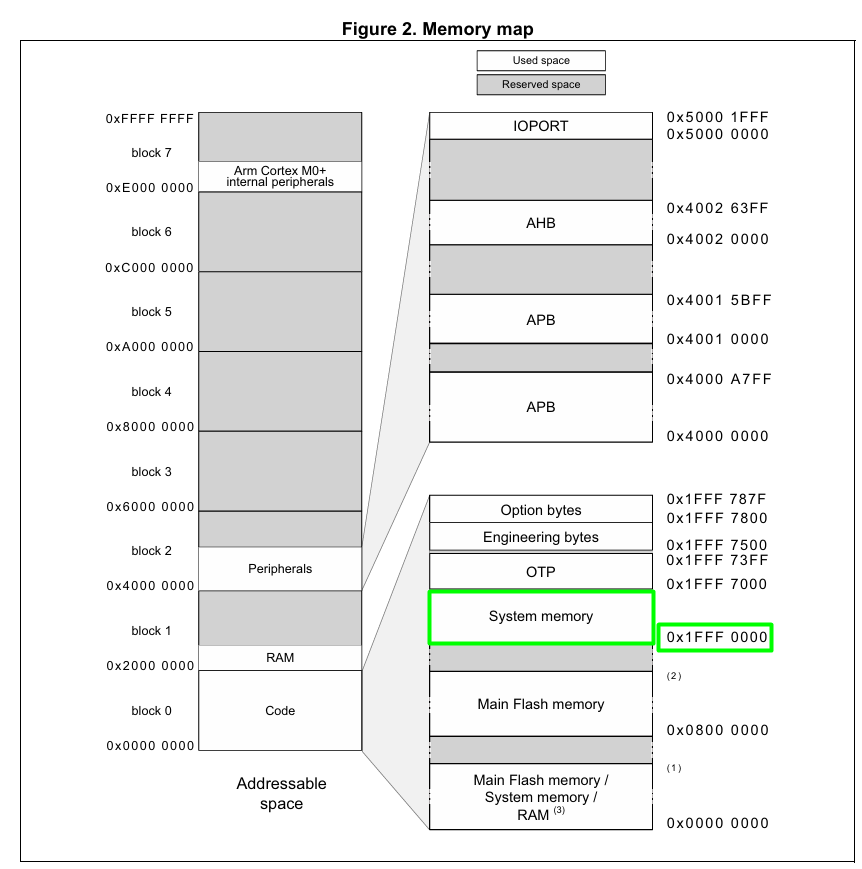
5. Flash and SRAM Mapping
The STM32 uses a flexible memory aliasing system. Depending on the boot mode, the selected memory is aliased to address 0x0000 0000, which is where the CPU expects to find the Initial Stack Pointer and the Reset Vector.
Common Memory Layout (Example: STM32G0):
- Main Flash: 0x0800 0000 (Your application code)
- System Memory: 0x1FFF 0000 (The built-in bootloader). This address is also something that changes on some STM32s. Refer to the Reference Manual to check all the addresses, for example
- SRAM: 0x2000 0000 (Runtime variables)
6. Hands-On Lab: Interfacing via AN3155 & CubeProg
In this experiment, we will bypass the standard SWD debugging interface and program the STM32G071RB via the AN3155 Serial Protocol. We will use the built-in ST-Link on the NUCLEO board, not as a debugger, but as a Virtual COM Port (VCP) bridge to the MCU’s UART pins.
Step 1: Hardware Configuration
- Identify the Entry Point: For the STM32G071, the system bootloader can be accessed via USART2 on pins PA2 (TX) and PA3 (RX). Conveniently, these pins are hardwired to the NUCLEO’s on-board ST-Link VCP.
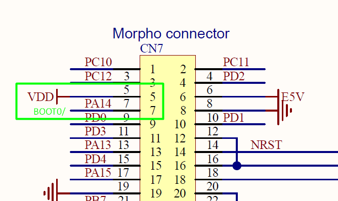
- Set the Boot Mode: Locate the BOOT0 pin on the NUCLEO headers (typically found on the CN7 or CN10 connectors). Use a jumper wire to tie BOOT0 to VDD (3.3V). CN7.5 and CN7.7 makes it easy:
- The Trigger: Press and release the Black Reset Button (B2). The MCU will now evaluate the BOOT0 pin and enter the System Memory bootloader instead of executing your main Flash code.
Step 2: Connection via STM32CubeProgrammer
- Connect the NUCLEO board to your PC via USB.
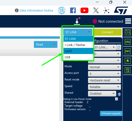
- Open STM32CubeProgrammer and switch the connection interface from “ST-LINK” to “UART” in the right-hand panel.
- Select the Port corresponding to the ST-Link Virtual COM Port (check Device Manager if unsure).
- Protocol Config: Set the Baudrate to 115200 and Parity to Even. (Even parity is a mandatory requirement for the AN3155 frame format).
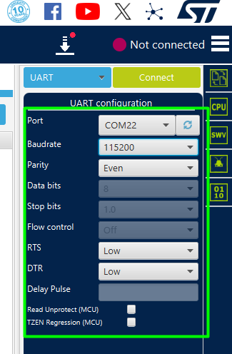
- Click Connect.
- If it fails to connect, double check if your option byte is limiting the entry pattern. On several STM32s, there is an empty check mechanism and you can leverage that to trigger the entry patterns by mass erasing the MCU and power cycling it.
Step 3: The Secret Handshake
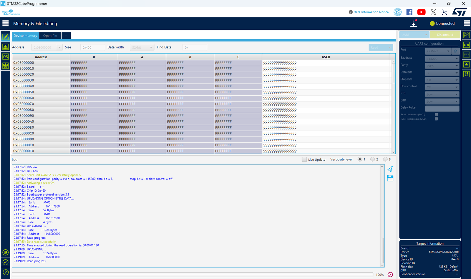
When you click “Connect,” CubeProg performs the AN3155 Auto-Baud detection. It sends the “Magic Byte” 0x7F. The STM32G0 uses the timing of this byte’s start and stop bits to calculate your PC’s baud rate and synchronize its internal clock. Without this handshake, the MCU remains silent. Once synchronized, CubeProg will display the chip’s memory content.
Step 4: Flash and Execution
- Go to the “Erasing & Programming” tab. Browse for your .bin or .hex file.
- Set the start address to 0x0800 0000 and click Start Programming.
- Return to Normal Mode: Once the log shows “File download complete,” remove the jumper wire from BOOT0 (so it returns to its default state, pulled low by the board’s internal resistor).
- Press the Reset Button again. The MCU will now skip the bootloader and execute your newly uploaded firmware.
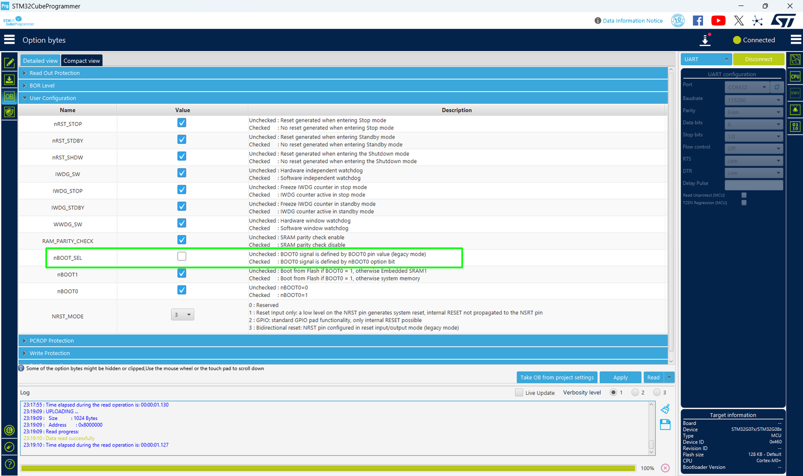
Note for STM32G0 Series: If the MCU still enters the bootloader after removing the jumper, check the Option Bytes (specifically nBOOT_SEL and nSWBOOT0). If nBOOT_SEL is cleared, the chip ignores the physical BOOT0 pin and relies on software bits instead. You can toggle these bits directly in the “Option Bytes” tab of CubeProg while still connected via UART!
7. Firmware and Option Bytes
Configuration via Option Bytes
While physical pins like BOOT0 are great for development, production devices often require more robust security or the ability to reconfigure boot behavior via software. This is handled by Option Bytes—a dedicated non-volatile memory area in the STM32.
Instead of writing complex HAL code to modify these, we can use the STM32CubeProgrammer GUI to manage security and boot behavior while connected via the UART bootloader.
Step1: Managing Boot Control (nSWBOOT0 & nBOOT_SEL)
For the STM32G071, you might want to disable the physical BOOT0 pin to prevent users from accidentally entering the bootloader.
- In CubeProg, click the “OB” (Option Bytes) icon in the left-hand menu.
- Expand the User Configuration menu.
- nBOOT_SEL: If this bit is checked, the MCU ignores the physical BOOT0 pin and instead looks at the nBOOT0 bit in the Option Bytes to decide where to boot.
- This allows you to “lock” the device into booting from Main Flash regardless of the hardware state.
Step2: Applying Changes
- Modify the desired bits in the GUI.
- Click “Apply”.
- The programmer will write the bytes and trigger an Option Byte Launch, which resets the MCU to load the new settings.
To avoid permanently losing access to the System Bootloader after disabling its physical hardware triggers via Option Bytes, you can implement a software-based ‘backdoor.’ By incorporating logic into your application code that triggers a jump to the System Memory address, you ensure the device remains recoverable for future updates. This advanced technique, where we can jump from application code to the System Bootloader, will be the focus of our next article.
Conclusion
Understanding the STM32 system bootloader is more than just a debugging trick; it is a fundamental pillar of robust embedded system design. By mastering the hardware configurations outlined in AN2606 and the serial communication nuances of AN3155, you gain the ability to design fail-safe update mechanisms and recovery paths for your devices. Whether you are using STM32CubeProgrammer for manual recovery or scripting your own Python-based flash tool, the built-in bootloader ensures that as long as your silicon is powered, your firmware is never truly out of reach.
Happy Coding =)