Code execution from SRAM on STM32 or other MCUs using the GCC.
Abstract
While STM32 microcontrollers typically execute code from Flash memory using the ART Accelerator to mask latency, certain scenarios require the deterministic speed of SRAM. This article demonstrates how to use GCC attributes and linker script modifications to relocate specific functions, interrupt handlers, or the entire firmware image to SRAM.
1. Introduction
In most embedded applications, the Flash memory is the default home for executable code. However, executing from SRAM can be a game-changer for specific use cases:
- Performance: SRAM offers zero-wait-state execution at maximum frequency, which is vital for timing-critical DSP or crypto algorithms.
- Power Consumption: By running from RAM, you can put the Flash memory into power-down mode, significantly reducing the current draw.
- Self-Programming: You cannot read/execute from Flash while writing to it, the famous Read-While-Write (RWW) feature, unless your MCU has dual bank memory. Executing the Flash-programming algorithm from RAM avoids CPU stalls and allows page erase/programming to be executed without hanging the MCU.
2. Prerequisites
To follow this tutorial, you will need:
- Hardware: Any STM32 board. We’ll use the NUCLEO-G071RB
- Software: STM32CubeIDE, STM32CubeMX and STM32Cube_FW_G0.
- Utility: STM32CubeProgrammer for configuring boot options.
- Firmware: Basics> STM32: How to use External Interrupts (EXTI) – Hacker Embedded.
3. Understanding the Linker Script
The Linker Script (.ld) is the blueprint for your binary. It defines two critical types of addresses for code sections:
- LMA (Load Memory Address): Where the code is stored (Flash).
- VMA (Virtual Memory Address): Where the code lives during execution (SRAM).
In a standard STM32 project, look for the .data section in your linker file. It usually contains a mapping like this:
					  /* Initialized data sections into "RAM" Ram type memory */
  .data :
  {
    . = ALIGN(4);
    _sdata = .;        /* create a global symbol at data start */
    *(.data)           /* .data sections */
    *(.data*)          /* .data* sections */
    *(.RamFunc)        /* .RamFunc sections */
    *(.RamFunc*)       /* .RamFunc* sections */

    . = ALIGN(4);
    _edata = .;        /* define a global symbol at data end */

  } >RAM AT> FLASH
The >RAM AT> FLASH syntax tells the linker: “Place this code in Flash, but link it as if it will run at an SRAM address.” At startup, the Reset_Handler in your assembly startup file (e.g., startup_stm32g0xx.s) executes a copy loop (LoopCopyDataInit) that moves this code from Flash to RAM.
4. Relocating a Single Function for code execution in SRAM
This article assumes that you are familiar with project creation and we’ll rely on a very simple EXTI associated with the onboard push button. If that is not the case, check this article for the very basics> STM32: How to use External Interrupts (EXTI) – Hacker Embedded.
To move a specific function to SRAM, we use the GCC section attribute.
Step 1: Attribute Declaration
In your main.c, declare your function with the .RamFunc attribute. This matches the section name defined in the linker script.
					/* USER CODE BEGIN PV */
uint32_t u32Sum;
/* USER CODE END PV */

/* Private function prototypes -----------------------------------------------*/
void SystemClock_Config(void);
/* USER CODE BEGIN PFP */
/* Function Prototype */
static uint32_t __attribute__((section(".RamFunc"))) Add(uint16_t x, uint16_t y);
/* USER CODE END PFP */

/* Private user code ---------------------------------------------------------*/
/* USER CODE BEGIN 0 */
uint32_t __attribute__((section(".RamFunc"))) Add(uint16_t x, uint16_t y)
{
	return (uint32_t) x+y;
}
/* USER CODE END 0 */

/**
 * @brief  The application entry point.
 * @retval int
 */
int main(void)
{

	/* USER CODE BEGIN 1 */

	/* USER CODE END 1 */

	/* MCU Configuration--------------------------------------------------------*/

	/* Reset of all peripherals, Initializes the Flash interface and the Systick. */
	HAL_Init();

	/* USER CODE BEGIN Init */

	/* USER CODE END Init */

	/* Configure the system clock */
	SystemClock_Config();

	/* USER CODE BEGIN SysInit */

	/* USER CODE END SysInit */

	/* Initialize all configured peripherals */
	MX_GPIO_Init();
	/* USER CODE BEGIN 2 */

	/* USER CODE END 2 */

	/* Infinite loop */
	/* USER CODE BEGIN WHILE */
	while (1)
	{
		/* USER CODE END WHILE */

		/* USER CODE BEGIN 3 */
		u32Sum = Add(1,2);
		HAL_Delay(200);
	}
	/* USER CODE END 3 */
}
Step 2: Implementation
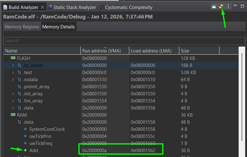
The function body remains standard C. When you build the project, the Build Analyzer will show this function’s address located within the SRAM range (typically in the initial 0x20000000s). Don’t forget to click in the refresh button first!
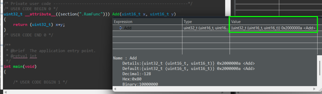
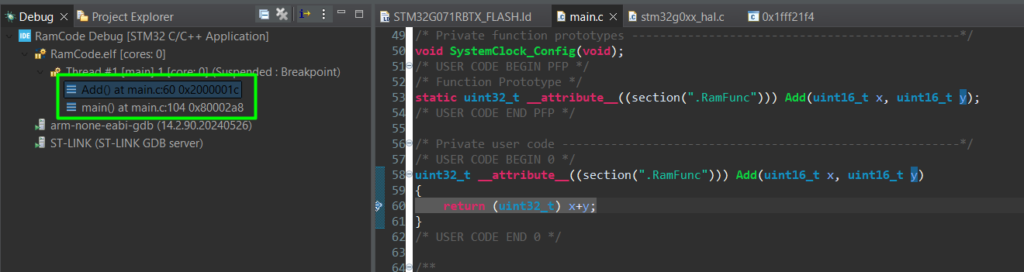
This can also be observed by hovering the mouse on top of the function once in debug mode:
Step 3: Verification
During a debug session, check the Program Counter (PC) or the Call Stack. When you step into Add function, the PC should jump from the 0x08… (Flash) range to the 0x20… (RAM) range.
5. Interrupt Handlers Executed in SRAM
Relocating ISRs are not that common, but might be useful under specific needs, typically high-speed applications. In these cases, we can move the IRQ Handler to run from RAM
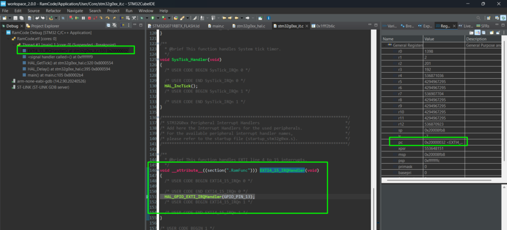
- Navigate to stm32g0xx_it.c.
- Apply the attribute to the desired handler:
					/**
  * @brief This function handles EXTI line 4 to 15 interrupts.
  */
void __attribute__((section(".RamFunc"))) EXTI4_15_IRQHandler(void)
{
  /* USER CODE BEGIN EXTI4_15_IRQn 0 */

  /* USER CODE END EXTI4_15_IRQn 0 */
  HAL_GPIO_EXTI_IRQHandler(GPIO_PIN_13);
  /* USER CODE BEGIN EXTI4_15_IRQn 1 */

  /* USER CODE END EXTI4_15_IRQn 1 */
}
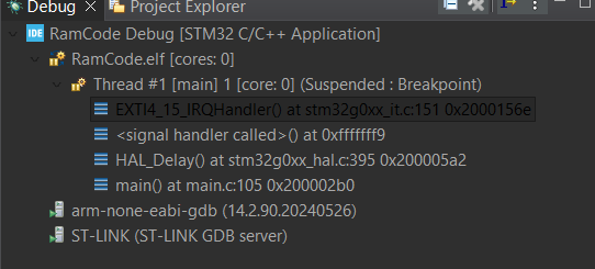
Note: Because the HAL_GPIO_EXTI_IRQHandler is still in Flash, the CPU will jump back to Flash to execute the HAL logic. For maximum performance, you should implement the entire logic within the SRAM-based ISR or move the HAL functions to RAM as well, which are more complex.
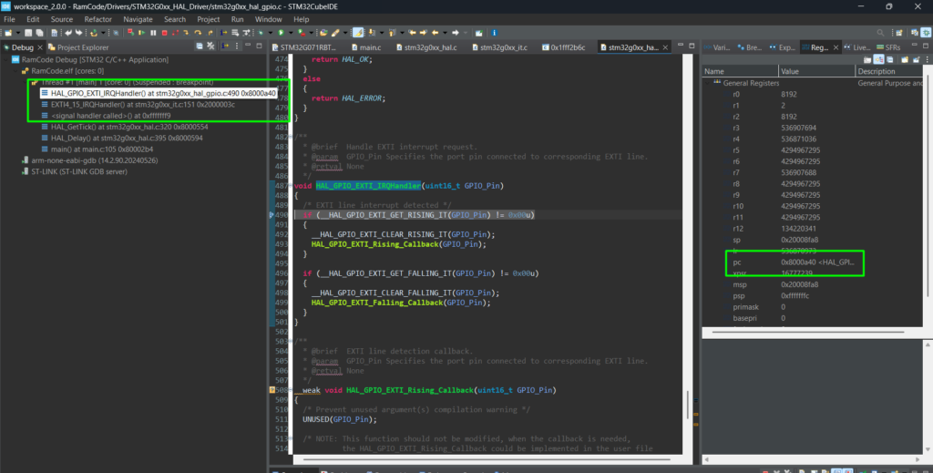
Entering the HAL_GPIO_EXTI_IRQHandler will move the code back into FLASH:
6. Executing the Entire Project from SRAM
In some cases, such as “In-Application Programming” (IAP) or even in case your application needs to perform a mass erase, you may need the entire firmware to run from RAM.
Step 1: Switch the Linker Script
STM32CubeIDE projects typically include two scripts: …FLASH.ld and …RAM.ld. This might not be true for all STM32s, so just to facilitate, here is the RAM.ld file content:
					/*
******************************************************************************
**
** @file        : LinkerScript_RAM.ld
**
** @brief       : Linker script for STM32G071RBTx running fully from RAM
**
******************************************************************************
*/

/* Entry Point */
ENTRY(Reset_Handler)

/* Highest address of the user mode stack */
_estack = ORIGIN(RAM) + LENGTH(RAM); /* end of "RAM" Ram type memory */

_Min_Heap_Size  = 0x200; /* required amount of heap */
_Min_Stack_Size = 0x400; /* required amount of stack */

/* Memories definition
 * NOTE: Code and data are all placed in RAM. FLASH is still declared
 *       for completeness but is not used as a load/run region.
 */
MEMORY
{
  RAM   (xrw) : ORIGIN = 0x20000000, LENGTH = 36K
}

/* Sections */
SECTIONS
{
  /* Vector table and startup code into RAM */
  .isr_vector :
  {
    . = ALIGN(4);
    KEEP(*(.isr_vector)) /* Startup code / vector table */
    . = ALIGN(4);
  } >RAM

  /* Program code in RAM */
  .text :
  {
    . = ALIGN(4);
    *(.text)           /* .text sections (code) */
    *(.text*)          /* .text* sections (code) */
    *(.glue_7)         /* glue arm to thumb code */
    *(.glue_7t)        /* glue thumb to arm code */
    *(.eh_frame)

    KEEP (*(.init))
    KEEP (*(.fini))

    . = ALIGN(4);
    _etext = .;        /* end of code */
  } >RAM

  /* Constant data in RAM (since we execute entirely from RAM) */
  .rodata :
  {
    . = ALIGN(4);
    *(.rodata)         /* .rodata sections (constants, strings, etc.) */
    *(.rodata*)        /* .rodata* sections (constants, strings, etc.) */
    . = ALIGN(4);
  } >RAM

  .ARM.extab (READONLY) :
  {
    . = ALIGN(4);
    *(.ARM.extab* .gnu.linkonce.armextab.*)
    . = ALIGN(4);
  } >RAM

  .ARM (READONLY) :
  {
    . = ALIGN(4);
    __exidx_start = .;
    *(.ARM.exidx*)
    __exidx_end = .;
    . = ALIGN(4);
  } >RAM

  .preinit_array (READONLY) :
  {
    . = ALIGN(4);
    PROVIDE_HIDDEN (__preinit_array_start = .);
    KEEP (*(.preinit_array*))
    PROVIDE_HIDDEN (__preinit_array_end = .);
    . = ALIGN(4);
  } >RAM

  .init_array (READONLY) :
  {
    . = ALIGN(4);
    PROVIDE_HIDDEN (__init_array_start = .);
    KEEP (*(SORT(.init_array.*)))
    KEEP (*(.init_array*))
    PROVIDE_HIDDEN (__init_array_end = .);
    . = ALIGN(4);
  } >RAM

  .fini_array (READONLY) :
  {
    . = ALIGN(4);
    PROVIDE_HIDDEN (__fini_array_start = .);
    KEEP (*(SORT(.fini_array.*)))
    KEEP (*(.fini_array*))
    PROVIDE_HIDDEN (__fini_array_end = .);
    . = ALIGN(4);
  } >RAM

  /* In a pure-RAM image, .data is already in RAM at load time.
     Keep _sidata/_sdata/_edata for compatibility with existing startup,
     but startup should *not* copy from FLASH, or _sidata should just equal _sdata. */

  _sidata = .; /* dummy: no separate load region */

  .data :
  {
    . = ALIGN(4);
    _sdata = .;        /* data start */
    *(.data)
    *(.data*)
    *(.RamFunc)
    *(.RamFunc*)

    . = ALIGN(4);
    _edata = .;        /* data end */
  } >RAM

  /* Uninitialized data (zero-initialized) in RAM */
  . = ALIGN(4);
  .bss :
  {
    _sbss        = .;
    __bss_start__ = _sbss;
    *(.bss)
    *(.bss*)
    *(COMMON)

    . = ALIGN(4);
    _ebss        = .;
    __bss_end__  = _ebss;
  } >RAM

  /* Heap and stack area */
  ._user_heap_stack :
  {
    . = ALIGN(8);
    PROVIDE( end  = . );
    PROVIDE( _end = . );
    . = . + _Min_Heap_Size;
    . = . + _Min_Stack_Size;
    . = ALIGN(8);
  } >RAM

  /* Remove information from the compiler libraries */
  /DISCARD/ :
  {
    libc.a   ( * )
    libm.a   ( * )
    libgcc.a ( * )
  }

  .ARM.attributes 0 : { *(.ARM.attributes) }
}
- Right-click your project > Properties > C/C++ Build > Settings.
- Go to MCU GCC Linker > General.
- Change the Linker Script path to point to the _RAM.ld file.
Step 2: Relocate the Vector Table
The Vector Table must also move. Open system_stm32g0xx.c and uncomment the following lines:
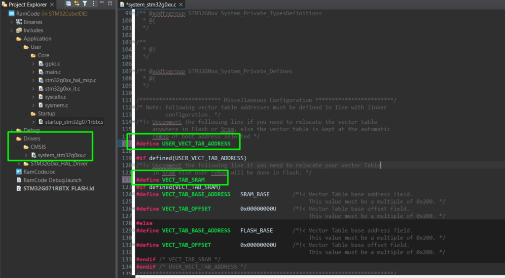
This updates the VTOR register at startup so the CPU knows where to find interrupt vectors in RAM.
Update the Build Analyzer to see the change after building:
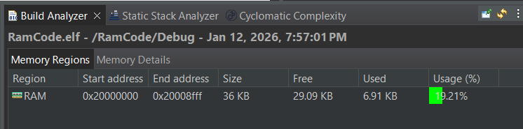
The entire code will be placed in RAM memory and of course, since no loading mechanism was put into place, this works only when using the debugger.
Here is the validation of the code running entirely from RAM:
Note: a few new STM32s have what they call flash-less MCU (H7R/S series) and actual flash-less devices, such as the N6, which have a bootloader system in place that copies the program memory from external flash and can either execute it with the internal RAM or directly from external FLASH. The secret is always in the linker script and basic C coding.
Conclusion
Moving code to SRAM is a powerful optimization technique. Whether you use the __attribute__((section(“.RamFunc”))) for specific bottlenecks or shift the entire project to RAM for power-down modes, understanding the interaction between the compiler, linker, and startup code is essential.
Table: Comparison of Execution Modes
Feature | Flash Execution | SRAM Execution |
Speed | Dependent on ART/Wait States | Deterministic (0-wait) |
Persistence | Permanent | Volatile (Lost on Power-off) |
Power | Higher (Flash active) | Lower (Flash can be off) |
Complexity | Default (Low) | Moderate (Linker tweaks) |