STM32 Tutorial: Delving into stm32-mw-openbl, AN3155, and Flash Programming on the NUCLEO-G071
Abstract
In our previous articles, we explored how to make the jump between a custom bootloader and an application, how to execute code from SRAM, and the mechanics of the STM32 factory system bootloader. Now, it is time to put all those concepts together into a production-ready solution.
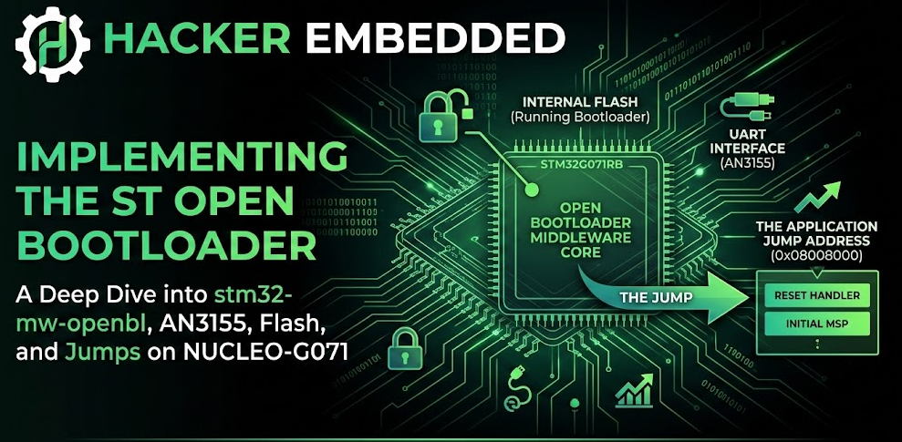
Instead of writing a command parser and flashing routines from scratch, we can leverage ST’s open-source middleware: the ST Open Bootloader (stm32-mw-openbl). In this tutorial, we will dive deep into the middleware’s architecture on GitHub, explore the UART communication protocol defined by AN3155, examine the exact C code responsible for programming the internal Flash memory, and finally execute the jump to the main application on a NUCLEO-G071 board.
1. Introduction to the Open Bootloader Middleware
The stm32-mw-openbl repository is STMicroelectronics’ official middleware for implementing In-Application Programming (IAP). It is designed to be a drop-in replacement for the immutable ROM System Bootloader, but with one massive advantage: you compile it, and it runs from User Flash.
This means you can customize it to support specific peripherals, add encryption, or perform custom hardware checks before booting. The middleware is split into three main layers:
Core: The protocol state machine that parses incoming bytes and executes commands.
Interfaces: Hardware abstraction (e.g., UART, I2C, SPI) that handles sending and receiving raw bytes.
Modules/Patterns: The memory drivers that actually erase and write to Flash or SRAM.
For this tutorial, we are targeting the NUCLEO-G071RB. We will configure the bootloader to communicate over UART and run directly from the base of the Flash memory (0x08000000), expecting our application to reside at 0x08008000.
2. The UART Protocol (AN3155)
When you use STM32CubeProgrammer over a serial port, it speaks a very specific language documented in ST’s Application Note AN3155. The stm32-mw-openbl middleware natively implements this exact protocol.
Here is how the communication flow works under the hood:
Synchronization: The host (your PC) starts by sending a single byte:
0x7F. The STM32 uses this byte to auto-detect the baud rate (if hardware auto-baud is enabled) and replies with an Acknowledge (ACK):0x79.Command Issuing: The host then sends a command byte followed by its bitwise complement (e.g., to send the “Write Memory” command
0x31, the host sends0x31 0xCE).Execution: If the bootloader supports the command, it replies with an ACK (
0x79), receives the payload (like memory addresses and data), executes the operation, and sends a final ACK. If anything fails, it replies with a Not-Acknowledge (NACK):0x1F.
By using the Open Bootloader middleware, all of this parsing, checksum verification, and ACK/NACK handling is automatically managed by the OpenBL_Core files.
3. Programming the Flash Memory
Since our bootloader receives firmware binaries over UART, it must write that data into the STM32G071’s Flash memory. The code responsible for this lives in the middleware repository under Interfaces/Patterns/FLASH/flash_interface.c.
Running from FLASH
An important concept here is that the bootloader itself is running from FLASH (at 0x08000000) while it writes to another sector of the same FLASH (at 0x08008000). On the STM32G071 (which typically has a single-bank Flash architecture), initiating a Flash erase or write operation will momentarily stall the CPU. The CPU halts instruction fetching until the Flash controller finishes the write. The HAL handles this natively, so we don’t need to force the execution into SRAM just to write to Flash!
Here is a simplified look at how flash_interface.c leverages the STM32 HAL to write incoming UART payloads into memory:
					#include "openbl_mem.h"
#include "stm32g0xx_hal.h"

/* Simplified excerpt based on stm32-mw-openbl / flash_interface.c */

void OPENBL_FLASH_Write(uint32_t Address, uint8_t *Data, uint32_t DataLength)
{
    uint32_t index = 0;

    /* 1. Unlock the Flash control register to allow writes */
    HAL_FLASH_Unlock();

    /* 2. Clear any pending error flags */
    __HAL_FLASH_CLEAR_FLAG(FLASH_FLAG_EOP | FLASH_FLAG_OPERR | FLASH_FLAG_WRPERR | FLASH_FLAG_PGAERR | FLASH_FLAG_PGSERR);

    /* 3. The STM32G0 programs Flash in Double-Words (64-bits / 8 bytes) */
    for (index = 0; index < DataLength; index += 8)
    {
        /* Cast the 8-byte array chunk into a 64-bit variable */
        uint64_t doubleWordData = *(uint64_t *)(Data + index);

        /* 4. Command the Flash Controller to program the double-word */
        if (HAL_FLASH_Program(FLASH_TYPEPROGRAM_DOUBLEWORD, Address + index, doubleWordData) != HAL_OK)
        {
            /* If write fails, lock flash and return NACK to the host */
            HAL_FLASH_Lock();
            OPENBL_Send_NACK();
            return;
        }
    }

    /* 5. Lock the Flash again to prevent accidental corruption */
    HAL_FLASH_Lock();
    OPENBL_Send_ACK();
}
When STM32CubeProgrammer sends the “Write Memory” (0x31) command over UART, the middleware core validates the address and passes the data payload directly to this function.
The actual code from the middleware is this one:
					/**
  * @brief  This function is used to write data in FLASH memory.
  * @param  Address The address where that data will be written.
  * @param  Data The data to be written.
  * @param  DataLength The length of the data to be written.
  * @retval None.
  */
void OPENBL_FLASH_Write(uint32_t Address, uint8_t *Data, uint32_t DataLength)
{
  uint32_t index  = 0U;
  uint32_t length = DataLength;

  if (length & 7U)
  {
    length = (length & 0xFFFFFFF8U) + 8U;
  }

  /* Unlock the flash memory for write operation */
  OPENBL_FLASH_Unlock();

  for (index = 0U; index < length; (index += 8U))
  {
    OPENBL_FLASH_ProgramDoubleWord((Address + index), (uint64_t)(*((uint64_t *)((uint32_t)Data + index))));
  }

  /* Lock the Flash to disable the flash control register access */
  OPENBL_FLASH_Lock();
}
4. The Final Step: The Jump to Application
Once the firmware update is complete, STM32CubeProgrammer sends the “Go” command (0x21) alongside the application’s base address (0x08008000).
As we discussed in our previous article, jumping from a bootloader to an application requires strict pre-flight cleanup. The Open Bootloader middleware handles this beautifully in its command execution sequence. When the Go command is parsed, the middleware calls a hardware-specific jump routine.
Here is the exact mechanism the Open Bootloader uses to pass execution to the newly programmed application:
					/**
  * @brief  This function is used to jump to a given address.
  * @param  Address The address where the function will jump.
  * @retval None.
  */
void OPENBL_FLASH_JumpToAddress(uint32_t Address)
{
  Function_Pointer jump_to_address;

  /* Deinitialize all HW resources used by the Bootloader to their reset values */
  OpenBootloader_DeInit();

  /* Enable IRQ */
  Common_EnableIrq();

  jump_to_address = (Function_Pointer)(*(__IO uint32_t *)(Address + 4U));

  /* Initialize user application's stack pointer */
  Common_SetMsp(*(__IO uint32_t *) Address);

  jump_to_address();
}
Which is essentially the same concept we used in the prevous article:
					typedef void (*pFunction)(void);

/* Executes the AN3155 'Go' Command */
void OPENBL_JumpToApp(uint32_t Address)
{
    uint32_t app_stack_pointer;
    uint32_t app_reset_handler;
    pFunction JumpToApplication;

    /* 1. Read the Stack Pointer and Reset Handler from the new vector table */
    app_stack_pointer = *(__IO uint32_t*)Address;
    app_reset_handler = *(__IO uint32_t*)(Address + 4);

    /* 2. Verify the Stack Pointer points to valid RAM (0x20000000 range for G071) */
    if ((app_stack_pointer & 0x2FFE0000) == 0x20000000)
    {
        /* 3. De-initialize peripherals used by the bootloader (UART, Clocks) */
        HAL_RCC_DeInit();
        HAL_DeInit();

        /* 4. Disable SysTick and clear its registers */
        SysTick->CTRL = 0;
        SysTick->LOAD = 0;
        SysTick->VAL  = 0;

        /* 5. Disable global interrupts to ensure a clean slate */
        __disable_irq();

        /* 6. Set the function pointer to the application's Reset Handler */
        JumpToApplication = (pFunction)app_reset_handler;

        /* 7. Set the Hardware Main Stack Pointer (MSP) */
        __set_MSP(app_stack_pointer);

        /* 8. Make the jump! Execution leaves the bootloader here. */
        JumpToApplication();
    }
    else
    {
        /* If the address is invalid, send NACK and stay in Bootloader */
        OPENBL_Send_NACK();
    }
}
Pro Tip: Do not forget that once the jump occurs, your newly executing Application must remap its Vector Table. On the STM32G071, you must update SCB->VTOR = 0x08008000; inside your SystemInit() or at the very beginning of main(), otherwise hardware interrupts will still trigger the bootloader’s handlers!
Conclusion
By studying the stm32-mw-openbl repository, we demystify what often feels like “black magic” in embedded systems. The ST Open Bootloader simply implements the standard AN3155 UART protocol to receive bytes, uses the standard HAL_FLASH_Program routines to write those bytes into Flash while momentarily stalling the CPU, and executes a well-calculated pointer jump to hand over control.
Integrating this middleware into your NUCLEO-G071 projects allows you to build a robust, production-ready OTA or serial update mechanism without reinventing the wheel—leaving you more time to focus on your core application logic.
Happy Coding =)