STM32: How to use DAC

STM32 HAL Tutorial: Generating Analog Signals from Digital Data

Abstract

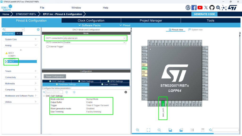
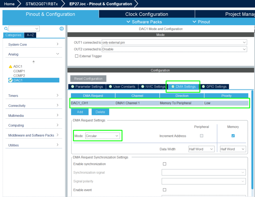
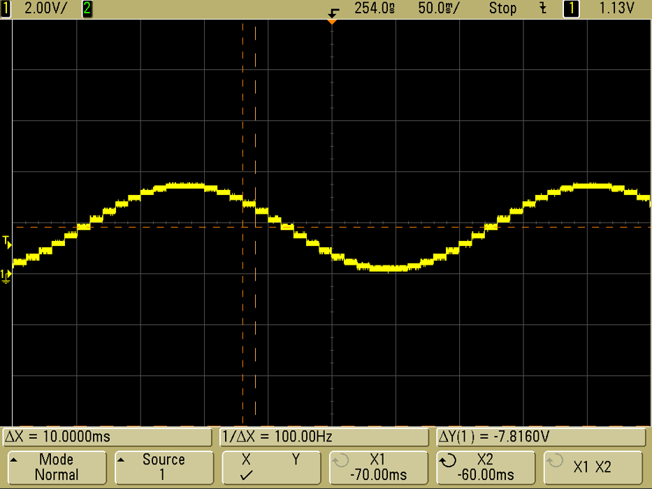
Learn how to configure and use the STM32 DAC with HAL and CubeMX. Step-by-step guide for analog signal generation, waveform output, and peripheral interfacing.

1. Introduction

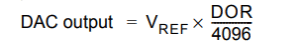
The DAC (Digital-to-Analog Converter) on STM32 allows you to generate analog voltages from digital values.

Applications include:

  • Audio signal generation
  • Analog sensor simulation
  • Voltage reference for other peripherals
  • Waveform generation (sine, triangle, PWM smoothing)

By the end of this episode, you’ll be able to:

  1. Configure DAC using CubeMX and HAL
  2. Output constant and variable voltages
  3. Generate simple waveforms using timers or DMA

2. Prerequisites

  • STM32 board with DAC peripheral (e.g., STM32G0, STM32G4, STM32H7)
  • STM32CubeIDE installed
  • Basic knowledge of HAL and GPIO

3. DAC Basics

  • Converts digital value (e.g., 12-bit number) to analog voltage
  • Output voltage formula:
  • Can operate in normal mode or triggered mode (timer or software)
  • Supports DMA for waveform generation

4. CubeMX Configuration

  1. Enable DAC peripheral

  2. Select DAC channel(s)

  3. Configure trigger (software, timer, or external)

  4. Enable DMA if waveform output is needed

  5. Generate initialization code

5. HAL Example: DAC Initialization

				
					DAC_HandleTypeDef hdac1;

void MX_DAC1_Init(void)
{
    DAC_ChannelConfTypeDef sConfig = {0};

    hdac1.Instance = DAC1;
    HAL_DAC_Init(&hdac1);

    sConfig.DAC_Trigger = DAC_TRIGGER_NONE;
    sConfig.DAC_OutputBuffer = DAC_OUTPUTBUFFER_ENABLE;

    HAL_DAC_ConfigChannel(&hdac1, &sConfig, DAC_CHANNEL_1);

    HAL_DAC_Start(&hdac1, DAC_CHANNEL_1);
}


6. Output a Constant Voltage

Converts digital value 2048 to ~1.65V if Vref = 3.3V

				
					uint32_t value = 2048; // Mid-scale (Vref/2)
HAL_DAC_SetValue(&hdac1, DAC_CHANNEL_1, DAC_ALIGN_12B_R, value);


7. Generate a Waveform

Example: Sine wave using DMA and timer trigger

				
					uint16_t sineWave[32] = {2048, 2447, 2831, 3185, 3495, ...}; // 12-bit values

HAL_DAC_Start_DMA(&hdac1, DAC_CHANNEL_1, (uint32_t*)sineWave, 32, DAC_ALIGN_12B_R);


Use timer to control update rate → frequency of waveform

8. Hands-On Lab Example

1. Initialize TIM6 to act as DAC’s trigger (100Hz)

2. Initialize DAC CHANNEL1

3. Configure the DMA

4. Create array of waveform samples (sine)

				
					/* USER CODE BEGIN PV */
uint16_t u16DACBuff[32] = {
		 2048, 2447, 2831, 3185, 3495, 3751, 3940, 4056,
		    4095, 4056, 3940, 3751, 3495, 3185, 2831, 2447,
		    2048, 1649, 1265,  911,  601,  345,  156,   40,
		       1,   40,  156,  345,  601,  911, 1265, 1649
};
/* USER CODE END PV */


5. Use DMA + timer trigger to generate continuous waveform

Tip: Use DAC + OpAmp for low-impedance analog signals suitable for sensors or actuators

9. Advantages of DAC

  • Converts digital signals to analog with high precision

  • Supports DMA and timers for continuous waveform generation

  • Can interface with OpAmps, ADCs, or external circuits

  • Essential for audio, control, and sensor applications

Leave a Comment

Your email address will not be published. Required fields are marked *

Scroll to Top