STM32 HAL Tutorial: Interfacing SPI via polling and interrupt
Abstract
Learn how to configure SPI communication on STM32 using CubeMX and HAL drivers. Step-by-step guide to use SPI in polling, IT and DMA modes.
1. Introduction
In previous episodes, we explored I²C communication with sensors.
Now we’ll learn about SPI (Serial Peripheral Interface), a high-speed protocol often used for:
- OLED or TFT displays
- External EEPROM and flash memory
- Sensors requiring fast data transfer
By the end of this episode, you’ll be able to:
Configure STM32 SPI peripheral using CubeMX.
2. Prerequisites
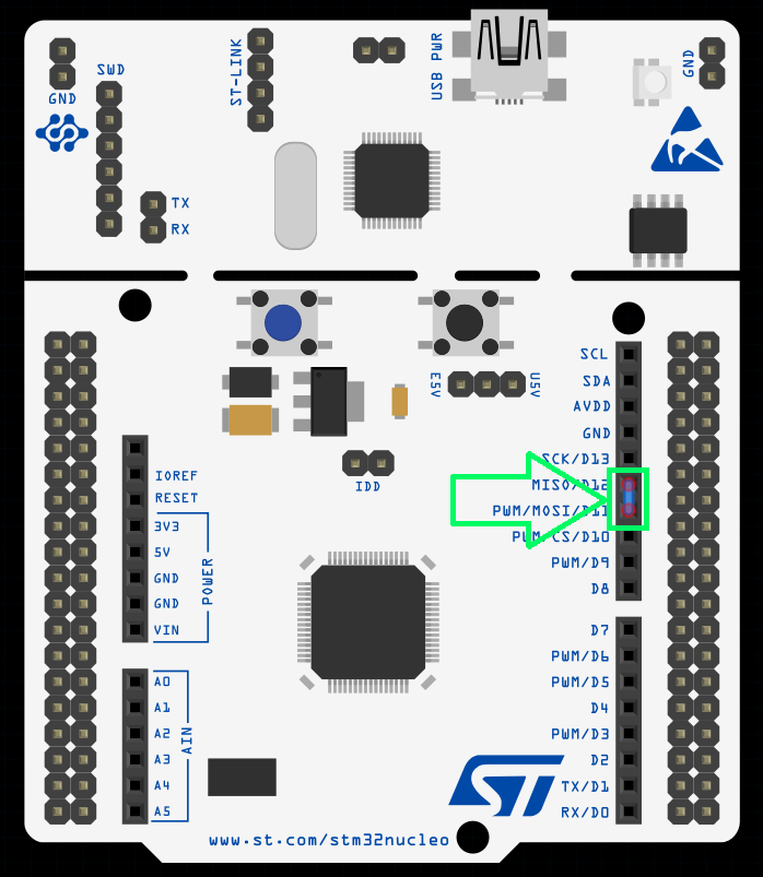
- STM32 board with SPI pins exposed (SCK, MOSI, MISO, CS).
- SPI device (e.g., OLED display SSD1306, or EEPROM like 25LC256).
- STM32CubeIDE installed.
3. Configuring SPI in CubeMX
Step 1 – Open Project
- Create a new project in STM32CubeMX.
Step 2 – Enable SPI Peripheral
- Go to Pinout & Configuration.
- Select SPI1 (or available SPI peripheral).
- Assign pins for:
- SCK – Clock / PB3
- MOSI – Master Out, Slave In / PB5
- MISO – Master In, Slave Out / PB4
- CS – No pin will be used on the loop back demo.
Tip: For a simple demo, in case you don’t have external components, you can create a hardware loopback by connecting MOSI and MISO together:
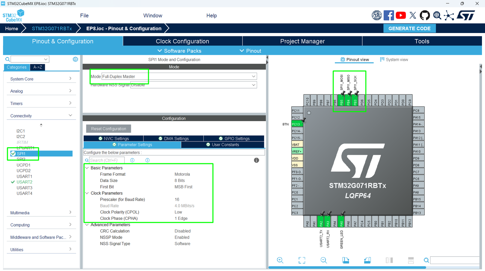
Step 3 – Configure Parameters
- Click SPI1 → Parameter Settings:
- Mode: Full-Duplex Master
- Data Size: 8 bits
- Clock Polarity/Phase: Check device datasheet (often CPOL = 0, CPHA = 0)
- Baud Rate Prescaler: Choose suitable speed – the Clock Configuration will impact the settings here, make sure to adjust your MCU’s frequency first
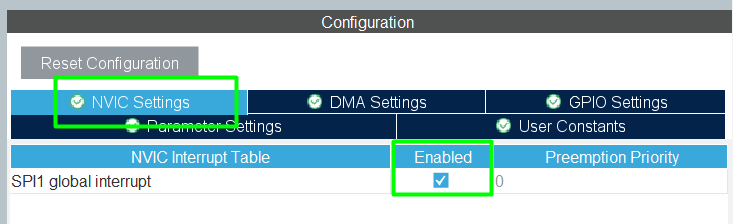
Step 4 – Enable NVIC Interrupt and DMA (Optional)
- For the hands on, only SPI NVIC will be used
Step 5 – Generate Code
Click Project → Generate Code to initialize HAL SPI structures.
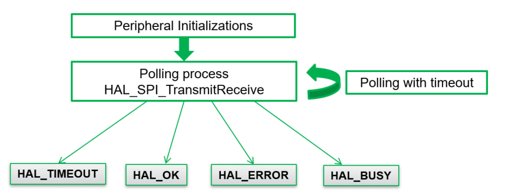
4. Sending/Receiving Data via SPI by polling
Example: Sending Multiple Byte
					/* USER CODE BEGIN PV */
uint8_t tx_buffer[10]={0,1,2,3,4,5,6,7,8,9};
uint8_t rx_buffer[10];
/* USER CODE END PV */

/* USER CODE BEGIN 2 */
HAL_SPI_TransmitReceive(&hspi1,tx_buffer,rx_buffer,10,100);
 /* USER CODE END 2 */
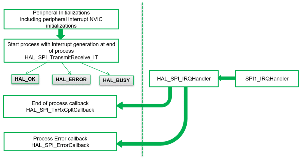
5. Sending/Receiving Data via SPI via IT
					/* USER CODE BEGIN PV */
uint8_t tx_buff[]={0,1,2,3,4,5,6,7,8,9};
uint8_t rx_buff[10];
/* USER CODE END PV*/

  /* USER CODE BEGIN 2 */
  HAL_SPI_TransmitReceive_IT(&hspi1,tx_buff,rx_buff,10);
  /* USER CODE END 2 */

/* USER CODE BEGIN 4 */
void HAL_SPI_TxRxCpltCallback(SPI_HandleTypeDef *hspi)
{
  HAL_GPIO_TogglePin(GPIOA, GPIO_PIN_5);
}
/* USER CODE END 4 */
Full Source Code: hackerembedded/STM32_EP8
6. Compiling and Running
- Build Project → Click hammer icon or press [Ctrl+B].
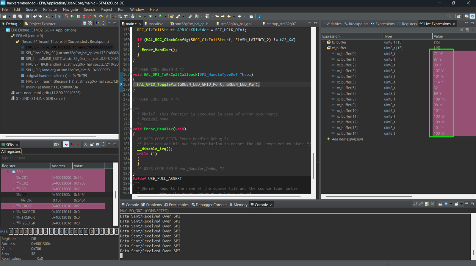
- Flash Project → Connect STM32 and run or enter in Debug Mode.
- Test SPI Communication:
- Place a breakpoint on the callback or monitor the LED
7. Hands-On Lab Recap
You learned:
- How to configure SPI peripheral in CubeMX.
- How to send and receive data with SPI using HAL.
- Basic HAL functions for full-duplex SPI communication.
SPI allows fast, reliable communication in embedded systems and is often used for displays, memory, and high-speed sensors.
8. Common Issues & Fixes
| Issue | Cause | Solution |
|---|---|---|
| SPI device not responding | Wrong SCK/MOSI/MISO pins | Verify CubeMX pinout |
| Display garbled | Wrong clock polarity/phase | Check device datasheet |
| Transmission error | CS pin not handled | Set CS LOW before transmit, HIGH after |
| Compilation error | HAL_SPI functions missing | Regenerate CubeMX code |