STM32 HAL Tutorial: Hardware Timers and Pulse-Width Modulation
Abstract
Learn how to configure STM32 hardware timers using CubeMX and HAL drivers. Step-by-step tutorial for generating periodic interrupts and PWM signals to control LEDs or motors.
1. Introduction
In previous episodes, we learned about GPIOs and external interrupts.
Now it’s time to explore STM32 hardware timers, which are essential for:
- Generating precise time delays without blocking the CPU.
- Creating PWM signals for LEDs, motors, and other devices.
- Scheduling periodic tasks using timer interrupts.
By the end of this episode, you’ll be able to:
- Configure a timer using STM32CubeMX.
- Generate periodic LED blinking with interrupts.
- Generate a PWM signal to control LED brightness.
2. Prerequisites
- STM32 development board (Nucleo, Discovery, or Blue Pill).
- STM32CubeIDE installed.
- Basic knowledge of GPIOs and EXTI (Episodes 2-4).
3. Configuring a Timer in STM32CubeMX
Step 1 – Open Your Project
- Open a new project in STM32CubeMX.
Step 2 – Add Timer Peripheral
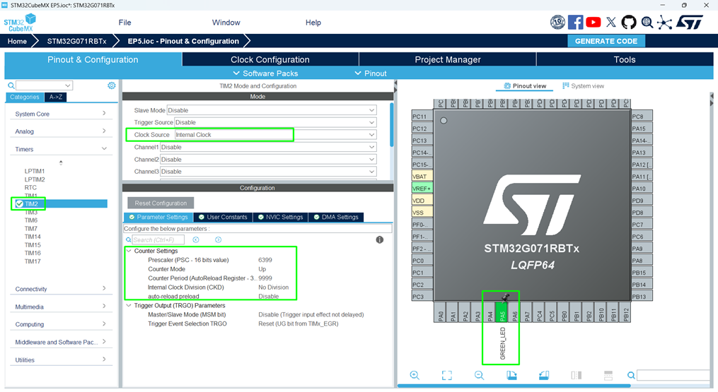
- Go to the Pinout & Configuration
- Select TIM2 (or any general-purpose timer available).
- Enable Internal Clock and set Mode:
- Internal Clock: Standard counting.
- PWM Generation: For controlling LED brightness.
Step 3 – Configure Timer Parameters
- Click Timer Configuration → Parameter Settings:
- Prescaler → Divides system clock to slow timer.
- Counter Period → Sets how long the timer counts before overflowing.
- Example for 1 Hz LED blink:
- System Clock: 64 MHz
- Prescaler: 6399 → Timer frequency = 10 kHz
- Period: 9999 → Overflow every 1 second
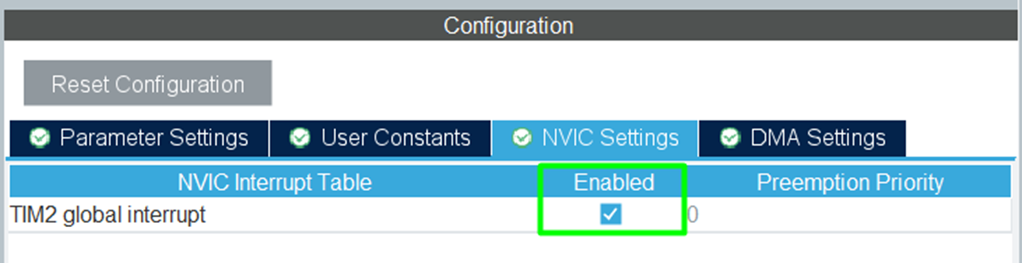
Step 4 – Enable Timer Interrupt
- Check Update Event (UIE) Interrupt.
- CubeMX generates the NVIC configuration for TIM2.
Step 5 – Generate Code
- Click Project → Generate Code.
4. Writing Timer Interrupt Code
Open main.c and locate HAL_TIM_PeriodElapsedCallback():
					void HAL_TIM_PeriodElapsedCallback(TIM_HandleTypeDef *htim)
{
    if(htim->Instance == TIM2) // Check the correct timer
    {
        HAL_GPIO_TogglePin(GPIOA, GPIO_PIN_5); // Toggle LED
    }
}
Before the main loop, call the
Code Explanation
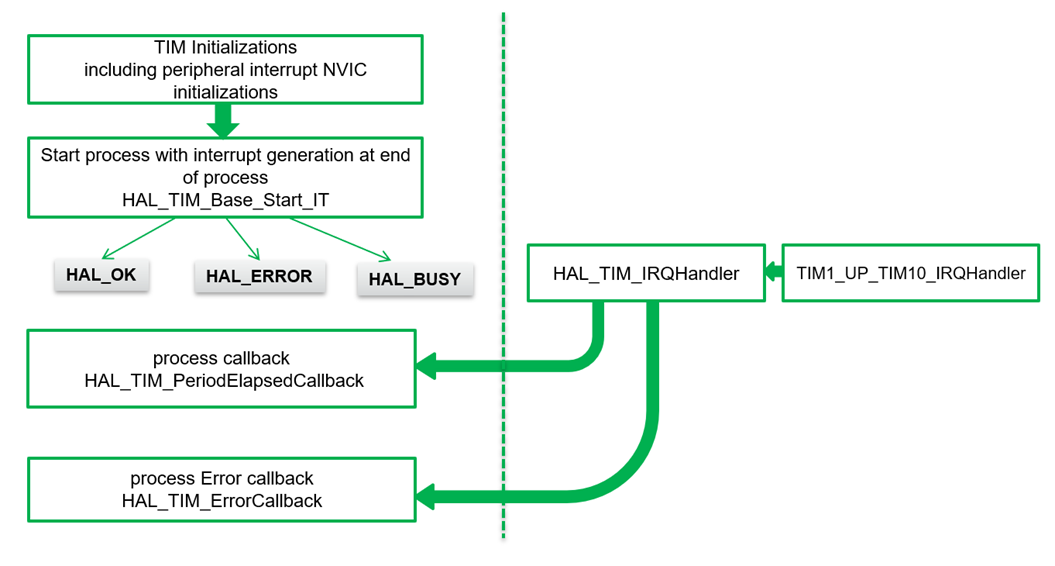
- The function runs automatically every time TIM2 overflows.
- The LED toggles without using HAL_Delay(), freeing CPU for other tasks.
6. Compiling and Running
- Build Project → Click hammer icon or press [Ctrl + B].
- Flash → Connect board and run or enter in debug mode.
- Test LED Blink → LED toggles at timer interval.
7. Generating PWM Signals
PWM (Pulse Width Modulation) is used to control:
- LED brightness
- Servo positions
- Motor speed
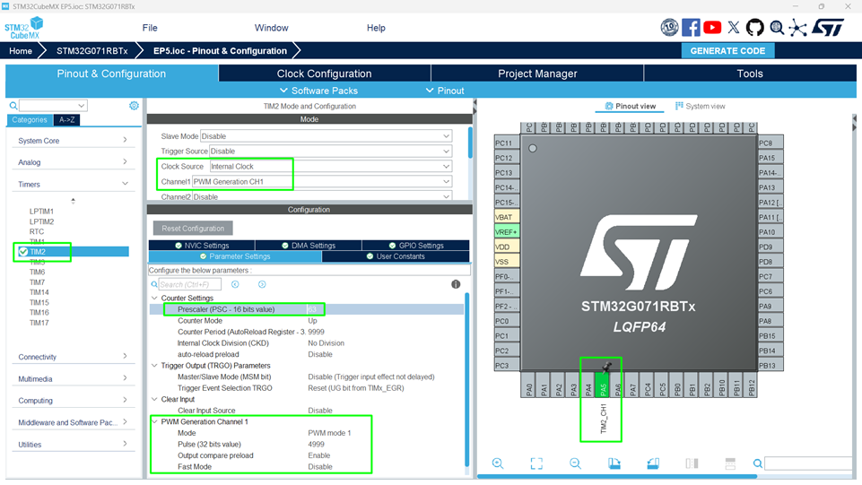
Step 1 – Configure PWM Channel
- In CubeMX, select TIM2 → PWM Generation Channel 1.
- Set PWM Mode to PWM1.
- Reduce the Prescaler to 63, that will increase the PWM frequency
- Adjust Pulse to control duty cycle (0–100%).
Step 2 – Write PWM Code
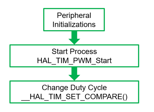
					HAL_TIM_PWM_Start(&htim2, TIM_CHANNEL_1); // Start PWM
__HAL_TIM_SET_COMPARE(&htim2, TIM_CHANNEL_1, 500); // 50% duty cycle
- __HAL_TIM_SET_COMPARE() sets the duty cycle.
Changing this value adjusts brightness.
					  HAL_Delay(200);
	  __HAL_TIM_SET_COMPARE(&htim2,TIM_CHANNEL_1, u16Compare);
	  if(u16Compare >= 9999)
		  u16Compare = 0;
	  else
		  u16Compare += 1000;
8. Compiling and Running
- Build Project → Click hammer icon or press [Ctrl + B].
- Flash → Connect board and run or enter in debug mode.
- Test LED Blink → LED toggles at timer interval.
- Test PWM → observe brightness or movement.
9. Hands-On Lab Recap
You learned how to:
- Configure STM32 timers in CubeMX.
- Generate periodic interrupts for precise LED blinking.
- Produce PWM signals to control LED brightness.
- Free the CPU from blocking delays.
Timers are fundamental for advanced applications, from motor control to real-time scheduling.
10. Common Issues & Fixes
| Issue | Cause | Solution |
|---|---|---|
| LED doesn’t blink | Timer not started | Call HAL_TIM_Base_Start_IT() in main |
| PWM not working | Incorrect channel or period | Check CubeMX channel and duty cycle |
| Compilation error | HAL_TIM functions missing | Regenerate CubeMX code |
| Interrupt not triggering | NVIC priority misconfigured | Verify CubeMX NVIC settings |
11. What’s Next
In Episode 6, we’ll explore UART (USART) communication:
- Sending and receiving data from PC or other devices.
- Using interrupts and DMA for efficient communication.
- Hands-on lab: Send “Hello STM32!” via serial port.