STM32 HAL Tutorial: Using Timer Interrupts for Responsive Analog-to-PWM Applications
Abstract
Learn how to use STM32 timer interrupts to read ADC values and update PWM output efficiently. Step-by-step guide for responsive sensor-to-actuator control using HAL.
1. Introduction
In previous episodes, we combined ADC readings with PWM to control LEDs or servos.
Now, we’ll make the system interrupt-driven, which:
- Reduces CPU blocking from polling loops
- Provides precise, periodic updates of PWM based on sensor input
- Improves responsiveness in multitasking applications
By the end of this episode, you’ll be able to:
- Configure TIMER interrupt.
- Read ADC values inside its own ISR.
Update PWM output in real-time without blocking the main loop.
2. Prerequisites
- STM32 board with ADC sensor (e.g., potentiometer)
- PWM output pin connected to LED
- STM32CubeIDE installed
Knowledge of ADC, PWM, and timers from Episodes 5, 9, and 10
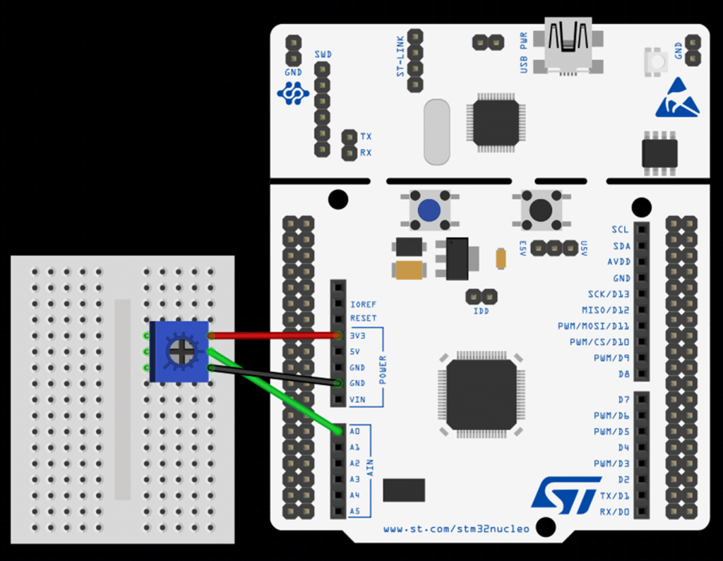
This image was made using Fritizing
3. Configuring ADC & TIM in CubeMX
Step 1 – Open Project
- Create a new project in STM32CubeMX.
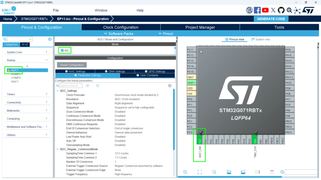
Step 2 – Enable ADC Peripheral
- Go to Pinout & Configuration.
- Select ADC1.
- Assign the analog pin (e.g., PA0) for your sensor.
- Click ADC1 → Parameter Settings:
- Resolution: 12-bit (0–4095 digital values)
- Data Alignment: Right
- Scan Conversion Mode: Disabled (single channel)
- Continuous Conversion Mode: Disabled
- Trigger the conversion in ISR
Step 3 – Configure Timer with Interrupt
- Enable TIM3 (or any general-purpose timer).
- Set period to desired ADC sampling interval (e.g., 10 ms for 100 Hz).
- Enable Update Interrupt to trigger HAL_TIM_PeriodElapsedCallback().
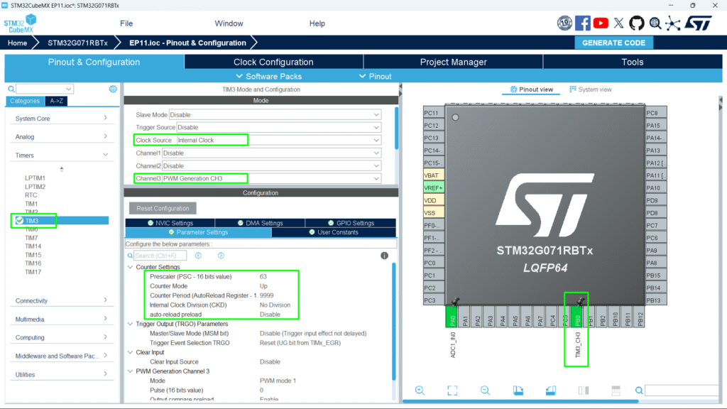
Step 3 – Configure PWM Channel
- TIM3_CH3 → PWM output pin (e.g., PB0).
- Set PWM mode and period as in Episode 10.
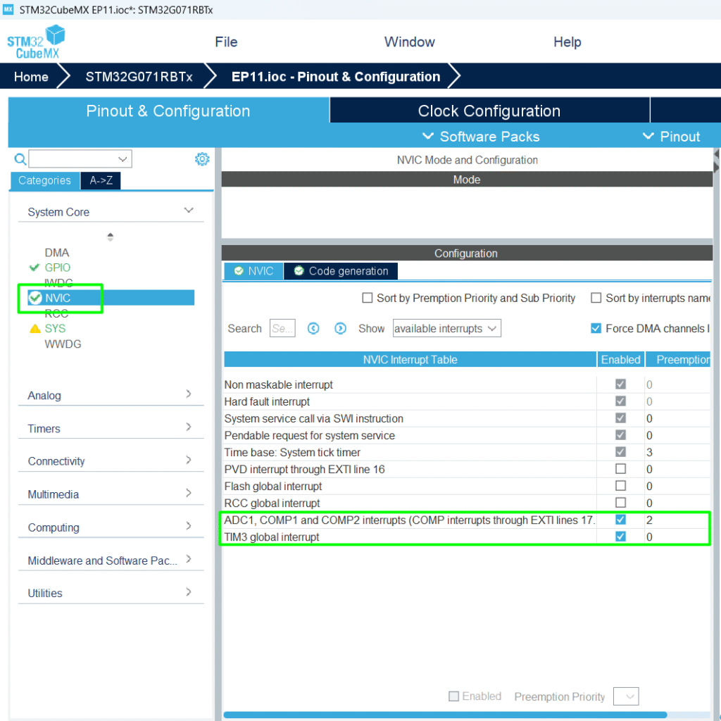
Step 4 – Configure NVIC Priority
- ADC priority level 2
- TIM3 priority level 0
Step 5 – Generate Code
Click Project → Generate Code to initialize HAL ADC structures.
4. Writing the ISRs callback
STM32CubeMX generates a callback function as weak, so the user needs to re-create them:
					/* USER CODE BEGIN 4 */
void HAL_ADC_ConvCpltCallback(ADC_HandleTypeDef *hadc)
{
	adcValue = HAL_ADC_GetValue(hadc);
}
void HAL_TIM_PeriodElapsedCallback(TIM_HandleTypeDef *htim)
{
	// Map ADC value to PWM duty cycle
	pwmValue = (adcValue * 9999) / 4095;
	// Update PWM output
	__HAL_TIM_SET_COMPARE(&htim3, TIM_CHANNEL_3, pwmValue);
	HAL_ADC_Start_IT(&hadc1);
}
/* USER CODE END 4 */
Code Explanation
- Timer ISR triggers at fixed intervals (e.g., every 10 ms).
- ADC conversion happens inside its own ISR.
- PWM duty cycle updates immediately, providing smooth control.
- Main loop can remain free for other tasks.
5. Hands-On main code
- The main loop is non-blocking and free.
- PWM output responds to ADC input automatically via interrupt.
					/* USER CODE BEGIN PV */
uint32_t adcValue = 0;
uint32_t pwmValue = 0;
/* USER CODE END PV */
					 /* USER CODE BEGIN 2 */
 HAL_ADCEx_Calibration_Start(&hadc1);
 HAL_ADC_Start_IT(&hadc1);
 HAL_TIM_Base_Start_IT(&htim3);
 HAL_TIM_PWM_Start(&htim3, TIM_CHANNEL_3);
 /* USER CODE END 2 */
Full Source Code: hackerembedded/STM32_EP11
6. Compiling and Running
- Build Project → Click hammer icon.
- Flash Project → Connect STM32 and run (Ctrl + F11).
- Test PWM Control:
- Rotate potentiometer → LED brightness changes.
- Main loop remains free to handle other tasks (e.g., UART communication, SPI, I²C sensors)
7. Advantages of Interrupt-Driven Approach
- Non-blocking operation → MCU can multitask efficiently
- Precise timing → PWM updates at exact intervals
- Smooth sensor-to-actuator mapping → No lag or flickering
- Scalable → Multiple ADC channels and PWM outputs can be handled in same ISR
8. Common Issues & Fixes
| Issue | Cause | Solution |
|---|---|---|
| LED not responding | Timer interrupt not started | Call HAL_TIM_Base_Start_IT() |
| ADC reading incorrect | Reading inside the wrong ISR | Adjust HAL_ADC_PollForConversion() timeout |
| Main loop blocked | ADC or PWM code outside ISR | Keep main loop free; ISR handles ADC→PWM |
| Main loop blocked | ADC ISR happening too often | Adjust the sampling time and triggering source |