STM32 HAL Tutorial: Mapping Analog Sensor Input to PWM Output
Abstract
Learn how to use STM32 ADC input to control PWM output using CubeMX and HAL drivers. Step-by-step guide for controlling LED brightness or servo motors based on analog sensors.
1. Introduction
In Episode 9, we learned how to read analog values using ADC.
Now we’ll combine ADC readings with PWM to create responsive applications:
- Control LED brightness based on potentiometer input.
- Control servo motor position using analog sensor.
This is a common technique in sensor-driven systems like robotics, lighting, and automation.
2. Prerequisites
- STM32 board with ADC pin connected to an analog sensor or potentiometer.
- PWM output pin (e.g., LED on PA5).
- STM32CubeIDE installed.
- Knowledge of ADC and Timers/PWM from Episodes 5 & 9.
- The hardware setup will be made by adding a potentiometer for the ADC
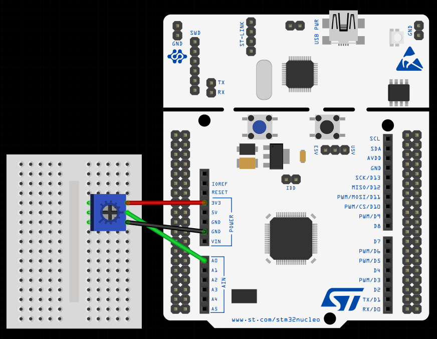
This image was made using Fritizing
3. Configuring ADC & TIM in CubeMX
Step 1 – Open Project
- Create a new project in STM32CubeMX.
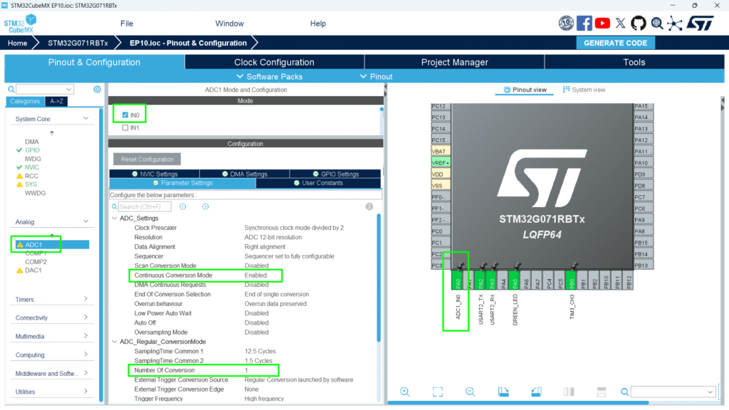
Step 2 – Enable ADC Peripheral
- Go to Pinout & Configuration.
- Select ADC1.
- Assign the analog pin (e.g., PA0) for your sensor.
- Click ADC1 → Parameter Settings:
- Resolution: 12-bit (0–4095 digital values)
- Data Alignment: Right
- Scan Conversion Mode: Disabled (single channel)
- Continuous Conversion Mode: Enable for continuous readings
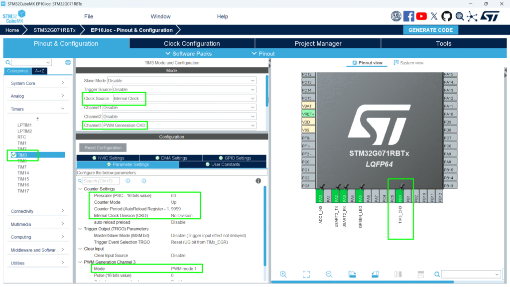
Step 3 – Configure Timer for PWM
- Enable TIM3 or another general-purpose timer.
- Set PWM mode 1, period = 9999 (or suitable for your application).
- Assign PWM channel (e.g., TIM3_CH3 → PB0).
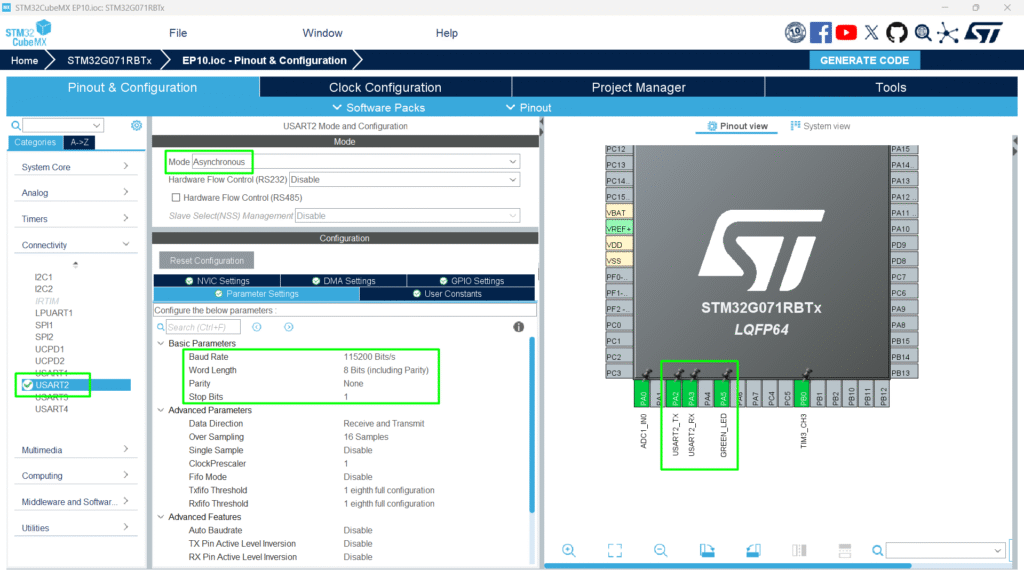
Step 4 – Optional
- Configure UART2 on PA2 and PA3 for printf
- Configure PA5 for the Green LED
Step 5 – Generate Code
Click Project → Generate Code to initialize HAL ADC structures.
4. Mapping ADC to PWM Duty Cycle
Follow the USER CODE to copy and paste into your own code.
					/* USER CODE BEGIN PV */
uint32_t adcValue = 0;
uint32_t pwmValue = 0;
/* USER CODE END PV */
					/* USER CODE BEGIN 2 */
 HAL_ADCEx_Calibration_Start(&hadc1);
 HAL_ADC_Start(&hadc1);
 HAL_TIM_PWM_Start(&htim3, TIM_CHANNEL_3);
 /* USER CODE END 2 */
					 /* USER CODE BEGIN WHILE */
 while (1)
 {
   /* USER CODE END WHILE */
   /* USER CODE BEGIN 3 */
	  if(HAL_ADC_PollForConversion(&hadc1, 100) == HAL_OK)
	  {
		  adcValue = HAL_ADC_GetValue(&hadc1);
		  pwmValue = (adcValue * 9999) / 4095;
		  __HAL_TIM_SET_COMPARE(&htim3, TIM_CHANNEL_3, pwmValue);
	  }
 }
 /* USER CODE END 3 */
Code Explanation
- Reads analog sensor via ADC.
- Maps 12-bit ADC value to timer period for PWM.
- Updates PWM output in real-time, controlling LED brightness or servo position.
5. Example: LED Brightness Control
- Connect an LED to PWM output pin.
- Rotate potentiometer → LED brightness changes smoothly.
Note: if HW262 or similar Arduino shield is used, make sure the voltage on the potentiometer A0 is not above 3.3V, as the STM32 is not a 5V MCU and anything beyond VDDA +0.3V can damage the board.
Full Source Code: hackerembedded/STM32_EP10
6. Compiling and Running
- Build Project → Click hammer icon.
- Flash Project → Connect STM32 and run (Ctrl + F11).
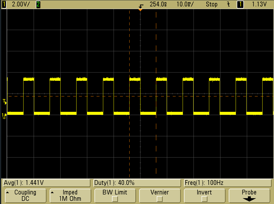
- Test PWM Control:
- Rotate potentiometer → LED brightness changes.
- Check the PB0 in the scope and play with the potentiometer
7. Hands-On Lab Recap
You learned:
- How to combine ADC input with PWM output.
- How to map analog sensor readings to PWM duty cycle.
- How to control LED brightness
- How to use HAL functions to achieve smooth sensor-driven control.
8. Common Issues & Fixes
| Issue | Cause | Solution |
|---|---|---|
| LED/servo not responding | ADC or PWM not started | Verify HAL_ADC_Start() and HAL_TIM_PWM_Start() |
| LED flickers | PWM duty cycle not updated properly | Ensure __HAL_TIM_SET_COMPARE() inside loop |
| Compilation errors | HAL functions missing | Regenerate CubeMX code |