
Getting started with Zephyr and STM32! Learn how to handle a push button with Zephyr and STM32
Abstract
Zephyr is a open-source and vendor neutral proven RTOS ecosystem, with a small memory footprint, usually less than 8KB FLASH and 5KB RAM and it’s made to be scalable, from small MCUs to complex multi-core systems. In this article series we’ll explore the Zephyr with STM32.
1. Introduction
This tutorial assumes you have already installed the Zephyr and its dependencies. You can follow the official installation guide:
Getting Started Guide — Zephyr Project Documentation
If you are new to Zephyr, follow ours: Hacker Embedded Getting Started with Zephyr and STM32
In this tutorial, we will create our own toggle LED application based on the push button. There are two ways to create a Zephyr application:
- Use the official example application.
- Create an application from scratch.
In this tutorial, we will use the example we did in the previous article: Hacker Embedded How to create your own Zephyr application with STM32 , but the same could be done by leveraging the existing example: https://github.com/zephyrproject-rtos/example-application
2. How to turn on the LED with the push button
Now that you have your own Zephyr application working based on this article: – Hacker Embedded How to create your own Zephyr application with STM32, let’s modify it so that the LED turns on when a button is pressed.
First, make sure that the Zephyr virtual environment (.venv) is activated. Your main.c file should contain the Blink LED application created in the previous tutorial:
					#include <zephyr/kernel.h>
#include <zephyr/drivers/gpio.h>

#define LED_NODE DT_ALIAS(led0)

static const struct gpio_dt_spec led = GPIO_DT_SPEC_GET(LED_NODE, gpios);

int main(void)
{
   gpio_pin_configure_dt(&led, GPIO_OUTPUT_ACTIVE);

   while (1) {
       gpio_pin_toggle_dt(&led);
       k_sleep(K_MSEC(200));
   }
}
Modifying the Application
To make the LED respond to a button press, we need to make a few changes to the code:
- Define a DeviceTree alias for the button.
- Create a GPIO specification for the button.
- Configure the button pin as an input.
- Read the button state inside the main loop.
- Turn the LED on or off depending on whether the button is pressed.
Replace the contents of main.c with the following code:
					#include <zephyr/kernel.h>
#include <zephyr/drivers/gpio.h>

#define LED_NODE DT_ALIAS(led0)
#define BUTTON_NODE DT_ALIAS(sw0)

static const struct gpio_dt_spec led = GPIO_DT_SPEC_GET(LED_NODE, gpios);
static const struct gpio_dt_spec button = GPIO_DT_SPEC_GET(BUTTON_NODE, gpios);

int main(void)
{
   gpio_pin_configure_dt(&led, GPIO_OUTPUT_ACTIVE);
   gpio_pin_configure_dt(&button, GPIO_INPUT);

   while (1) {
       int val = gpio_pin_get_dt(&button);

       if (val == 1){
           gpio_pin_set_dt(&led, 0);
       } else {
           gpio_pin_set_dt(&led, 1);
       }
       k_sleep(K_MSEC(50));
   }
}
Understanding the Changes
The following line creates a DeviceTree alias for the user button:
#define BUTTON_NODE DT_ALIAS(sw0)
The button GPIO is then obtained from the DeviceTree:
static const struct gpio_dt_spec button = GPIO_DT_SPEC_GET(BUTTON_NODE, gpios);
Next, the button is configured as an input:
gpio_pin_configure_dt(&button, GPIO_INPUT);
Inside the main loop, the application reads the current state of the button:
int val = gpio_pin_get_dt(&button);
If the button is pressed (val == 1), the LED is turned on. Otherwise, it is turned off.
Finally, the application waits 50 ms before checking the button again.
3. Configuring the Project for Your Board
Now you need to configure the project for your development board.
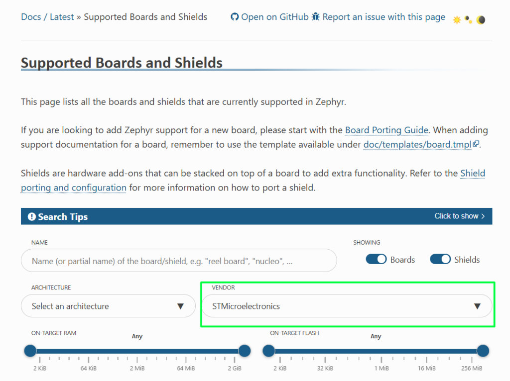
Open the list of supported ST boards:
Supported Boards and Shields — Zephyr Project Documentation
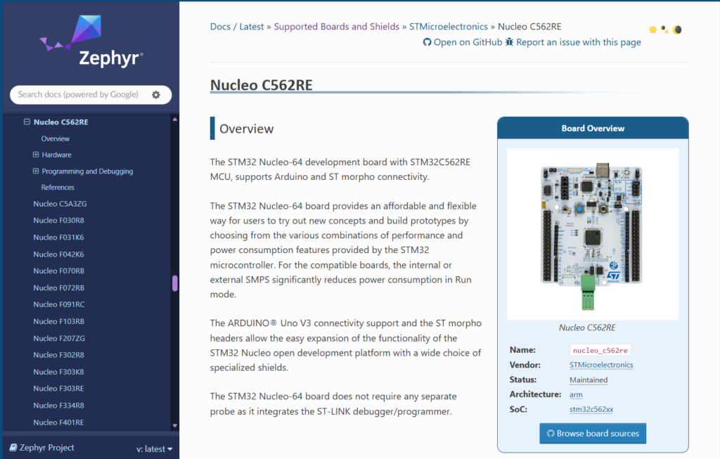
Locate your board. In this tutorial, we will use the NUCLEO-C562RE board.
The Zephyr board name is the same as the one shown in the URL: Nucleo C562RE — Zephyr Project Documentation
Tips and Tricks when using a different STM32 board
Rename the Overlay File
Inside the boards folder, rename the overlay file to match your board name:
b_u585i_iot02a.overlay (for example)
Modify sample.yaml
Open sample.yaml and update the integration_platforms section:
integration_platforms:
– custom_plank
– b_u585i_iot02a
If you are using a different board, replace b_u585i_iot02a with your board’s Zephyr name.
Modify prj.conf
Open prj.conf.
Remove:
CONFIG_BLINK=y
and replace it with:
CONFIG_GPIO=y
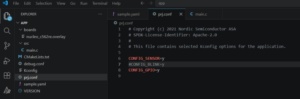
This enables the GPIO driver, which is required for controlling the LED.
4. Building and Flashing the Application
Build the project:
west build -p always -b nucleo_c562re .
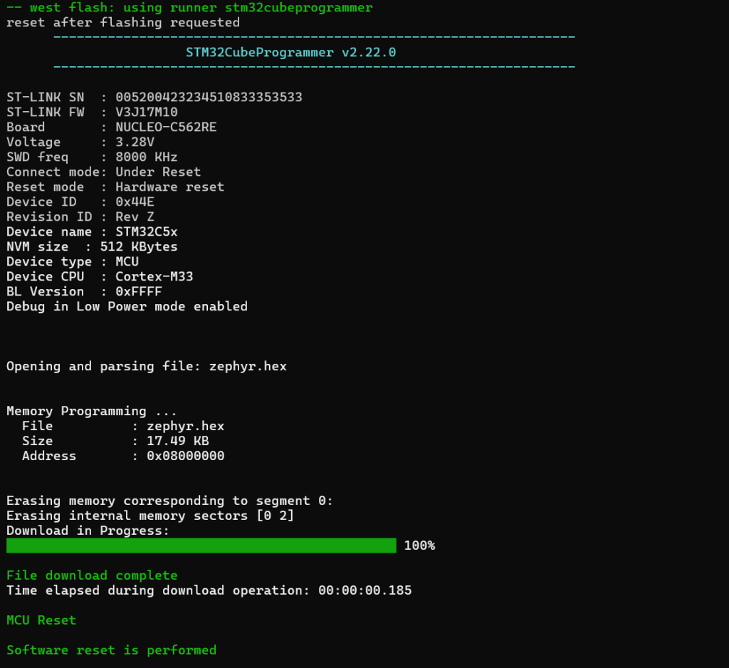
Program the built code to the board:
west flash
Your custom Blink LED application should now be running.
Tips and Tricks – Creating a Build Alias
Since you will build the application frequently, creating a shell alias can save time.
Open your .bashrc file:
nano ~/.bashrc
Add the following line at the end:
alias build="west build -p always -b b_u585i_iot02a ."
Save the file and reload it:
source ~/.bashrc
From now on, you can build your project simply by typing: build
Tips and Tricks – How to change the board
If you are using a different board, replace b_u585i_iot02a with your board name. In this case, we’ve used the new nucleo_c562re

You can reflash the project on the new board using the same command:
west flash
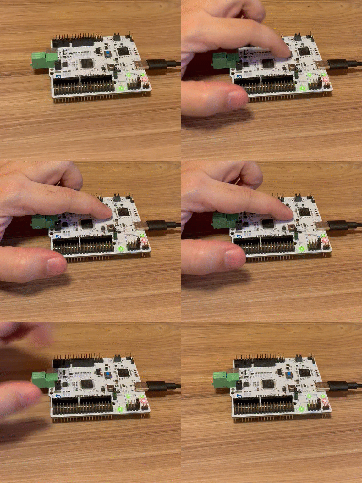
After the board resets, pressing the user button should turn the LED off. Releasing the button should turn the LED on.
Happy Coding =)